
think3D has added reverse engineering to its list of offerings to achieve its vision “One stop shop for all 3D printing needs”. With a team of highly qualified professionals, think3D can provide advance innovative approach to save your re-engineering time & cost. For any reverse engineering requirement, please drop an email to info@think3d.in

Upload files in Get Quote section and get quote within 4 hrs

Technically qualified team in various mfg. technologies

Highly competitive price and bulk discounts also available

All designs and data are kept in highly secure private server
Reverse-engineering is the act of dismantling an object to see how it works. It is done primarily to analyze and gain knowledge about the way something works but often is used to duplicate or enhance the object. Many things can be reverse-engineered, including software, physical machines, military technology and even biological functions related to how genes work.
The practice of reverse-engineering as applied to computer hardware and software is taken from older industries. Software reverse-engineering focuses on a program’s machine code — the string of 0s and 1s that are sent to the logic processor. Program language statements are used to turn the machine code back into the original source code.
Depending on the technology, the knowledge gained during reverse-engineering can be used to repurpose obsolete objects, do a security analysis, gain a competitive advantage or simply to teach someone about how something works. No matter how the knowledge is used or what it relates to, reverse-engineering is the process of gaining that knowledge from a finished object.
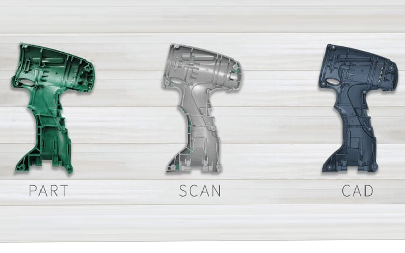
The purpose of reverse-engineering is to find out how an object or system works. There are a variety of reasons to do this. Reverse-engineering can be used to learn how something works and to recreate the object or to create a similar object with added enhancements.
In the first stage in the process, sometimes called “pre- screening,” reverse engineers determine the candidate product for their project. Potential candidates for such a project include singular items, parts, components, units, subassemblies, some of which may contain many smaller parts sold as a single entity.
The second stage, disassembly or de-compilation of the original product, is the most time-consuming aspect of the project. In this stage, reverse engineers attempt to construct a characterization of the system by accumulating all of the technical data and instructions of how the product works.
In the third stage of reverse engineering, reverse engineers try to verify that the data generated by disassembly or de-compilation is an accurate reconstruction of the original system. Engineers verify the accuracy and validity of their designs by testing the system, creating prototypes, and experimenting with the results.
The final stage of the reverse engineering process is the introduction of a new product into the marketplace. These new products are often innovations of the original product with competitive designs, features, or capabilities. These products may also be adaptations of the original product for use with other integrated systems, such as different platforms of computer operating systems. Main Concepts of Manual Reverse Engineering:
MAIN CONCEPTS OF MANUAL REVERSE ENGINEERING:
Manual reverse engineering can be described as the form of RE that does not uses any machine to take the dimensions of the component in concern. A particular sequence of steps then has to be followed to reverse engineer which is as follows.
PRODUCT DISSECTION
First step is to take apart the subject throughout. All the parts has to be taken apart of that subject without causing any damage to any part without forgetting their arrangement.
MEASUREMENTS WITH ROUGH DRAWING
All the dimensions have to be recorded of all the parts of the disassembled subject on a rough drawing of all the respective parts. These should be good enough to be easily understood by the user. The rough drawing serves a great purpose while creating their 3D model on any CAD software.
3D MODELLING
After recording all the dimensions, last step is to create the 3D CAD model on any software. Several software are available now a days to allow easy modelling of the subject. Different parts can be modelled separately and finally while creating the complete model. All the different part models can be assembled together as one. In any assembly drawing, it is highly convenient to show the exploded view of the complete subject so that it becomes easy to understand the assembly.
RAPID PROTOTYPING:
Rapid Prototyping refers to the fabrication of three dimensional physical models directly from a computer- aided design. The advantage of building a part in layers is that it allows you to build complex shapes that would be virtually impossible to machine, in addition to more simple designs
Geomagic® Control X™ is a professional 3D quality control and dimensional inspection software that lets you capture and process the data from 3D scanners and other portable devices to measure, understand, and communicate inspection results to ensure quality everywhere. Inspection isn’t just for metrology specialists. Geomagic Control X empowers everyone to measure, understand, and make decisions about their parts faster,more often, and more completely—from anywhere.
PolyWorks|InspectorTM is a universal 3D dimensional analysis and quality control software solution to control tool or part dimensions, diagnose and prevent manufacturing and assembly issues, guide assembly building through real-time measurements, and oversee the quality of assembled products by using portable metrology devices and CNC CMMs.
Industry acclaimed software for professional 3D scanning and data processing. Artec Studio features the most advanced 3D data algorithms which give you high precision in your results, while at the same time make 3D scanning intuitive and user-friendly.
PC-DMIS, Pro, CAD++, Touch
PC-DMIS is the world’s most popular CMM software for the collection, evaluation, management and presentation of manufacturing data. Our software is standard on Hexagon Metrology measurement devices and is also available on a wide range of non-Hexagon equipment. Use it to fully leverage your manufacturing process and build truly lean systems.PC-DMIS Portable brings powerful metrology tools to the shop floor.
GOM Inspect is a software for analyzing 3D measuring data from fringe projection or laser scanners, coordinate measurement machines (CMM) and other measuring systems. The GOM software is used in product development, quality control and production.
Basic: Support Removal, Sanding, Smoothing
Add on: Primer, Coating/ Painting
Think3D has been a great partner for us in supplying COVID-19 test cartridges on-time despite the pandemic challenges. When we came up with a new requirement needing a workforce of more than 25 people, think3D took up the challenge and arranged the workforce within 2 days. I highly recommend think3D for any manufacturing needs.
Sanket Srivatsav
Production In-Charge, Molbio
As a professor doing research on new materials, I needed a strong industry partner to assist us. think3D perfectly fit that bill. think3D team is highly knowledgeable on all manufacturing technologies and the team is very prompt in responding to all our requests. My research has been very successful, thanks to think3D team.
Dr. Karthik Chetan V
Asst. Professor, BITS Pilani

We found issue with one part at the time of assembly and needed a quick replacement. think3D team has quickly responded to our request, redesigned the part and printed it using metal 3D Printing and delivered in 3 days time. The part came out really well and the design was better than that of the actual one.
Rama Krishna
Senior Manager (IMM), BDL
3D scanning is the fast and accurate process of using a 3D scanner to convert physical objects into digital 3D data (in the most basic terms, it quickly and accurately gets your part into the computer). These scanners capture xyz coordinates of millions of points all over an object to recreate it digitally.
3D scanning saves money and especially time at every point of the manufacturing process, anywhere from design to production.
Generally,no. Almost any material lends itself to 3D scanning. Although 3D laser scanners can have trouble with black, translucent or reflective objects (for obvious reasons), these objects can either be sprayed with a flat white talc powder or can be scanned with a different type of 3D scanner. It would be an extremely rare case if we could not scan an object because of its material.
Absolutely not. The lasers used in 3D laser scanning will not damage parts, and are even safe for your eyes.
Our average 3D scanners are accurate to +/- 50 microns, or .002 in (two thousandths of an inch) for any point in space’s xyz coordinate. This is generally more than enough accuracy to cover the needs of almost all 3D scanning projects. If greater accuracy is required, we have options that use specialized 3D scanners which can provide finer scan data.
Yes. While 3D scanners do not directly output parametric data, our experienced engineers can reverse engineer fully parametric models based on the 3D scan data.
3D scanning initially creates an output that is inherently different from what CAD programs understand. CAD programs use mathematics to define a shape and control its behavior.
3D scanners output a collection of points (a point cloud) which are measured from the object using xyz-coordinates. While this collection of points digitally visualizes the physical shape of an object, there is no mathematical relationship between the individual points.
These 3D scanning software packages allow for the vital conversion of the point clouds into mathematical data that CAD programs can understand. While some manufacturing processes can work with point data (SLA, and some CAM/machining), most cases require mathematical data for the file to be usable.
Generally, you can scan all visible not-too-shiny surfaces that do not move for at least a few seconds of scanning time. The 3D scanner range we offer can scan an object size of 60-500 mm, but can be adapted for scanning small objects with fine details or larger object like a car engine.
The best objects to scan with this 3D scanner are:
Start calibrating with the mid-point and then calibrate smaller or larger sizes. It’s easier to calibrate this way.
You can export the 3D models directly from the scanner software to all the standard formats: .dae, .fbx, .ma, .obj, .ply, .stl, .txt, .wrl, .x3d, .x3dz, .zpr
© Copyright 2014 – 24 THINK3D. All rights reserved
Please fill the below form and you will receive brochure on your email id.