
Think3D has one EOS M290 machine in-house to offer various metal additive manufacturing service. We can 3D Print various metals like Aluminium, Maraging steel, Stainless steel, Inconel, Cobalt Chrome & Titanium.

Upload files in Get Quote section and get quote within 4 hrs

Technically qualified team in various mfg. technologies

Highly competitive price and bulk discounts also available

All designs and data are kept in highly secure private server
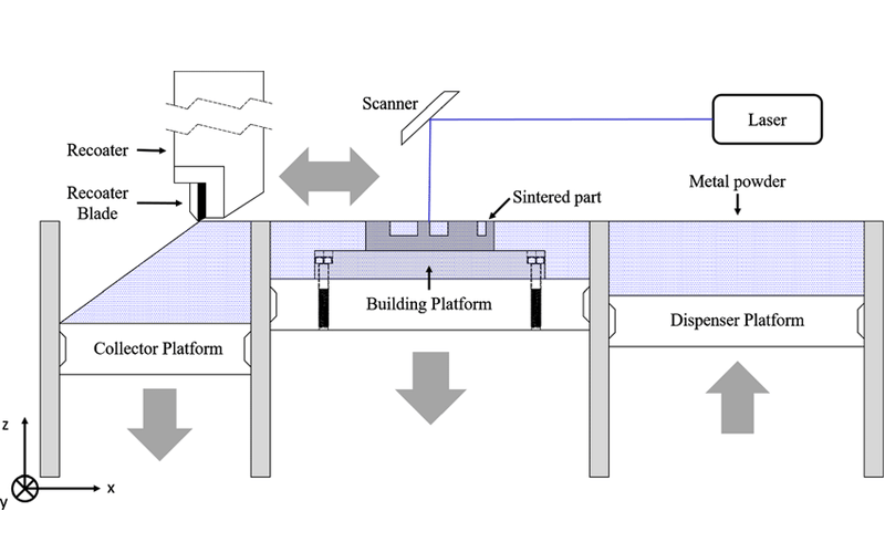
The DMLS machine begins sintering each layer—first the support structures to the base plate, then the part itself—with a laser aimed onto a bed of metallic powder. After a cross-section layer of powder is micro-welded, the build platform shifts down and a recoater blade moves across the platform to deposit the next layer of powder into an inert build chamber. The process is repeated layer by layer until the build is complete.
Support structures are automatically generated and built simultaneously in the same material, and are later manually removed. An initial brushing is manually administered to parts to remove a majority of loose powder, followed by the appropriate heat-treat cycle while still fixtured in the support systems to relieve any stresses. Parts are removed from the platform and support structures are removed from the parts, then finished with any needed bead blasting and deburring. Final DMLS parts are near 100 percent dense.
This technology combines the design flexibility of 3D Printing with the mechanical properties of metal. From tooling inserts with cooling channels to lightweight structures for aerospace, any application that involves complex metal parts potentially benefits from Metal 3D Printing.
DMLS materials are generally accepted to be equal or better than those of wrought materials. DMLS is also ideal when the geometry or structure of the part is not possible in any other process (for weight saving designs using honeycomb or latice structures for example). Think3D can also produce parts for implant medical applications. We also offer a number of secondary services such as painting, post machining and measurement and inspection, to further enhance the finish of your 3D-printed project design.
| Tensile Strength (MPa) | part density | Surface roughness | Melting Temperature °C |
|---|---|---|---|
| 340 | 2.67 g/cm3 | Ra 6 - 15 µm; Rz 50 - 100 µm | 600 |
| Tensile Strength (MPa) | part density | surface roughness | Melting Temperature °C |
|---|---|---|---|
| 2080 | 8.0-8.1 g/cm³ | Ra 4-6.5 µm; Rz 20-50 µm | 800 |
| Tensile Strength (MPa) | part density | surface roughness | Melting Temperature °C |
|---|---|---|---|
| 62.63 | 7.9 g/ cm³ | Ra 4 µm; Rz 20 µm | 1200 |
| Tensile Strength (MPa) | part density | surface roughness | Melting Temperature °C |
|---|---|---|---|
| 1210 | 8.15 g/cm³ | Ra 4 – 6.5 µm, Rz 20 - 50 µm | 1400 |
| Tensile Strength (MPa) | part density | surface roughness | Melting Temperature °C |
|---|---|---|---|
| 1350 | 8.3 g/cm³ | Ra 4 -10 µm; Rz 20 – 40 µm | 1450 |
| Tensile Strength (MPa) | part density | surface roughness | Melting Temperature °C |
|---|---|---|---|
| 1075 | 4.41 g/cm3 | Ra 5 - 9 µm; Rz 20-50 µm | 1100 |
Minimum Wall thickness:0.8 – 1 mm
Minimum details size: 2 mm (for text/ hole diameters etc)
Layer thickness: 0.02 – 0.08 mm
Max dimensions: 250 x 250 x 325 mm
Standard Accuracy:± 0.2% (with lower limit on ± 0.2 mm)
Lead Time: Minimum 3 – 8 working days for dispatch
Surface finish: Rough surface, which can undergo finishing stages as per requirement
Basic: Powder removal, Heat Treatment, EDM wire cut, Bead blasting, Polishing.
Add on: CNC Machining & Painting
Think3D has been a great partner for us in supplying COVID-19 test cartridges on-time despite the pandemic challenges. When we came up with a new requirement needing a workforce of more than 25 people, think3D took up the challenge and arranged the workforce within 2 days. I highly recommend think3D for any manufacturing needs.
Sanket Srivatsav
Production In-Charge, Molbio
As a professor doing research on new materials, I needed a strong industry partner to assist us. think3D perfectly fit that bill. think3D team is highly knowledgeable on all manufacturing technologies and the team is very prompt in responding to all our requests. My research has been very successful, thanks to think3D team.
Dr. Karthik Chetan V
Asst. Professor, BITS Pilani

We found issue with one part at the time of assembly and needed a quick replacement. think3D team has quickly responded to our request, redesigned the part and printed it using metal 3D Printing and delivered in 3 days time. The part came out really well and the design was better than that of the actual one.
Rama Krishna
Senior Manager (IMM), BDL
It depends on 2 factors quantity & complexity of parts.
For < 10 parts DMLS is cost effective. When our requirement is mass i.e > 1000 casting will be cheaper.
For simple geometries like a 50 mm Dia x 50mm Length shaft DMLS cost 15,000 bucks. where as in casting or machining it may costs max 2,000 bucks. So for complex geometries DMLS will be cheaper.
Costing is divided in 3 steps. Pre-processing, 3D printing and post processing. Pre-processing activity includes Designing, part feasibility, Reverse Engineering. Secondly, in the printing phase, the cost is dependent on number of factors such as build hours, support structure required, material, orientation of part etc. Finally, in the post processing phase, activities such as heat treatment, surface finish ,CNC machining, EDM etc activities do contribute. Every part doesn’t have to go through all above mentioned activities. Number of activities depend on case to case.
3D printed parts produced with DMLS process are quite accurate. This process can achieve near net shape of a part with 0.2 mm (200µm) accuracy. Additionally, CNC machining can be done for further improvement up to 5-10 µm.
Parts have Ra values ranging from 7-12 µm depending on the material, but we can alter the value by post processing activities. These activities are capable of producing ‘Matt Finish’ and ‘Mirror surface finish’ where matt finish hardly removes any material from the surface, around 200-300 mg. However, mirror surface finish needs 0.5-1 mm additional stock for achieving 1-2 Ra value. Matt finish can achieve up to 3-5 Ra.
In most of the cases, heat treatment is compulsory. During metal 3D printing process, residual stresses generated within the part geometry can lead to product failure while in application, and therefore, stress relieving heat treatment cycle is a must for functional parts. On the other hand, parts which are merely showpieces/non-functional can be delivered without being heat treated.
Threads have several over hangs where non removable supports were generated & pitch also cannot be maintained in printing.
Recommended process is, printing a plane hole without threads & later doing tapping.
Inert atmosphere is needed while sintering metal powders to avoid oxidation process.To maintain inert atmosphere we use Argon or Nitrogen gases.
In DMLS, chamber temperature will be of max 200°C. A 400 watt laser exposes on loose powder & generates 1500 – 2000 °C at 80 microns dia spot.
After DMLS printing there are a series of secondary process involved which comes time.
Below mentioned are series of steps we do in DMLS printing process.
© Copyright 2014 – 24 THINK3D. All rights reserved
Please fill the below form and you will receive brochure on your email id.
One reply on “DMLS”
Metal murti mass production