Categories
Latest News Learning Center

Voltran, a new EV charging startup

THINK3D is proud to have worked with VOLTRAN, an EV charging startup in supplying components for the DC 60 KW chargers developed by VOLTRAN to be deployed across various locations in India.

VOLTRAN is an EV charging startup founded by the founders of THINK3D. Having mastered the various manufacturing processes over the last 8 years, THINK3D management team decided to launch its own product. That culminated in setting up a new company, VOLTRAN ELECTRIC LLC to set up EV fast charge hubs across highways in India. For these fast charge hubs, VOLTRAN has taken assistance of THINK3D to manufacture components for the DC fast chargers. THINK3D has done the sheet metal work for the chassis, bus bars and CNC machining of the various components. With the expertise gained, THINK3D is now confident to serve the booming EV market. 

About VOLTRAN: VOLTRAN is an EV charging startup founded by the founding team of THINK3D. VOLTRAN is into setting up DC Fast Charge hubs across highways in India. Each hub consists of 5 60KW DC fast chargers, a lounge facility, restroom and office space. Each hub is open 24/7, so customers can comfortably drive on the highways without having this range anxiety. The first hub is coming up at Suryapet on Hyderabad – Vijayawada highway. At VOLTRAN, we shall also install DC fast chargers for customers looking to set up DC fast chargers at their locations. Please visit www.voltran.in to learn more.  

About THINK3D: THINK3D was founded in the year 2014 with a mission to democratize 3D Printing in India. The company slowly expanded into CNC Machining, Injection Molding, Sheet Metal, Vacuum Casting to become a full fledged manufacturing company. In 2018, the company has set up a state-of-art manufacturing facility in Visakhapatnam with various industrial 3D Printers, CNC Machines, Injection Molding machines all at one place. Please visit www.think3d.in to learn more.


Categories
Latest News Learning Center

What is Design For Manufacturing (DFM)

Design For Manufacturing (DFM) is the process of designing parts, components or products for ease of manufacturing with an ultimate goal of making a better product at a lower cost. This is done by simplifying, optimizing and refining the product design. In general, five principles are thoroughly examined during DFM. They are:

    • Process
    • Design
    • Material
    • Environment
    • Compliance / Testing

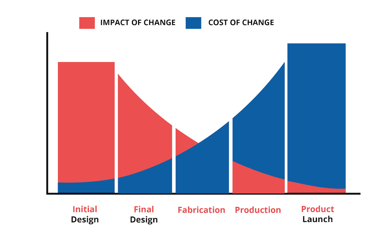
DFM should occur very early in the design process, right at the start of the product design process. As the design progresses through the product life cycle, it becomes very expensive to make changes and also very difficult to implement those changes. Early DFM allows design changes to be executed quickly at the least expensive location.

Also, a well executed DFM should include all stakeholders – engineers, designers, contract manufacturers, mold builders and material suppliers. The fundamental intent of this “cross-functional” DFM is to challenge the design at all levels – component, sub-system, system and holistic levels to ensure the design is optimized and does not have unnecessary cost embedded in it.

Pulling all the stakeholders together early in the design process is easier if a new product is being developed. But if we are dealing with an established product, challenging the original design is a necessary element of a thorough DFM process. Many a lot of times, mistakes in the original design are repeated by replicating a previous design. Always question every aspect of the design.

  • Look at the original drawings
  • Tear down the product
  • Look at competitive and near-neighbor products
  • Talk to vendors / contract manufacturers

DFM is the most important exercise any product designer should do before embarking on the product development. Unlike software development where bug can be resolved by pushing in a new line of code, in case of hardware, it isn’t possible. Costly recall of hardware products is required if there is any faulty part in the product.

Let us take a closer look at the above mentioned 5 different factors

PROCESS
Manufacturing process is the first aspect to be looked into when designing a product. Manufacturing process chosen must be the most optimal one for the product. Different manufacturing processes have different MOQ requirements for the product to become price competitive. One has to thus choose the process carefully. You wouldn’t want to use highly capitalized process like injection molding which involves building of tools and dies to make a low-volume part that could have been manufactured using a lower-capitalized method, such as thermoforming. When determining the manufacturing process, one should take into consideration the following – quantity of parts being made, the material being used, complexity of the surfaces, the tolerances required and whether there were secondary processes required.

DESIGN
Good design is essential for a good product. The actual drawing of the part or product has to conform to good manufacturing principles for the manufacturing process you’ve chosen. In case of plastic injection molding, the following principles would apply:

  • Constant wall thickness. This allows for consistent and quick part cooling
  • Appropriate draft (1 – 2 degree)
  • Texture – need 1 degree for every 0.001” of texture depth on texture side walls
  • Ribs = 60 percent of nominal wall
  • Simple transitions from thick to thin features
  • Wall thickness not too small
  • No undercuts or features that require side action – all features “in line of pull/mold opening”
  • Spec the loosest tolerances that allow a good product

Always be sure to discuss the design with your contract manufacturer who can ensure that your design conforms to good manufacturing principles for the selected process.

MATERIAL
It is also very important to select the correct material for the product. Below are some material properties to consider during DFM

  • Mechanical properties – How strong should the material be?
  • Optical properties – Should the material be reflective or transparent?
  • Thermal properties – How heat resistant does it need to be?
  • Color – What color does the part need to be?
  • Electrical properties – Does the material need to act as a dielectric?
  • Flammability – How flame/burn resistant does the material need to be?

Always make sure you discuss the  material with your contract manufacturer before deciding on the material to be used.

ENVIRONMENT
The product must be designed to withstand the environment it will be subjected to. Different materials have different properties like electrical conductivity, corrosion resistance and so on. Make sure the product is designed to function properly under its normal operating conditions.

COMPLIANCE / TESTING
All products must comply with safety and quality standards. Sometimes these are industry standards, others are third-party standards and some are internal, company-specific standards.

FEW ADDITIONAL FACTORS TO TAKE INTO CONSIDERATION
The goal of DFM is to reduce manufacturing costs without reducing performance. In addition to the principles of DFM, here are five factors that can affect design for manufacturing and design for assembly:

1. Minimize Part Count: Reducing the number of parts in a product is the quickest way to reduce cost because you are reducing the amount of material required, the amount of engineering, production, labor, all the way down to shipping costs.

2. Standardize Parts & Materials: Personalization and customization are expensive and time-consuming. Using quality standardized parts can shorten time to production as such parts are typically available and you can be more certain of their consistency. Material is based on the planned use of the product and it’s function. Consider:

  • How should it feel? Hard? Soft?
  • Does it need to withstand pressure?
  • Will the part or product need to conduct heat, electricity?

3. Create Modular Assemblies: Using non-customized modules / modular assemblies in the design allows one to modify the product without losing its overall functionality. A simple example is a basic automobile that allows you to add in extras by putting in a modular upgrade.

4. Design For Efficient Joining: Can the parts interlock or clip together? Look for ways to join the parts without the use of screws, fasteners or adhesives. If you must use fasteners, here are a few tips

  • Keep the number, size and variation of fasteners to a minimum
  • Use standard fasteners as much as possible.
  • Use self-tapping and chamfered screws for better placement.
  • Stay away from screws that are too long or too short, separate washers, tapped holes, round heads and flatheads.

5. Minimize Reorientation Of Parts During Assembly & Machining: Parts should be designed so that a minimum of manual interaction is necessary during production and assembly.

6. Streamline Number Of Manufacturing Operations / Processes: The more complex the process of making the product, the more variables for error are introduced.

7. Define Acceptable Surface Finishes: Unless it must be trade show grade, go with function rather than flashy for your surface finish.

10 OUTCOMES OF AN EFFECTIVE DFM
Below are 10 generally accepted Design for Manufacturing principles that were developed to help designers decrease the cost of and complexity of manufacturing a product. The results of a successful DFM are quantifiable in a host of ways.

  1. Minimize the number of product parts: Reducing the number of parts in the product is an easy way to lower the cost of product as it reduces the amount of material and assembly labor required. Reducing the number of parts also means less engineering, production, labor and shipping costs.
  2. Use standardized parts wherever possible: Customization is not only expensive, it is also highly time consuming. Use standardized parts as much as possible. Standardized parts are made to meet the same quality metrics, every time and they are already tooled. So you save costs and you won’t have to wonder whether they’ll pass inspection.
  3. Create a modular design: Using modules can simplify any future product redesign, and also allows for use of standard components and the re-use of modules in other projects.
  4. Design multi-functional parts: Design parts with more than one function. It is a simple way to reduce the total number of parts.
  5. Design multi-use products: Different products can share parts that have been designed for multi-use. Can your product use standardized parts that can be used in multiple products?
  6. Design for ease of fabrication: Choose the ideal combination between the material and manufacturing process that shall minimize production costs. Generally designers opt for very tight tolerances which is an absolute no-go. Avoid expensive and labor intensive final operations as painting, polishing and finish machining.
  7. Design product to join without using screws, fasteners, adhesives: Is it possible for your product to interlock or clip together without the need for any screws / rivets? Screws add only about 5% to the material cost but add 75% to the assembly labor. Wherever fasteners are required, try to keep the size, number and type to a minimum and use standard fasteners wherever possible.
  8. Design part to minimize handling during production and assembly: Handling includes positioning, orienting and fastening the part into place. For orientation purposes, use symmetrical parts wherever possible.
  9. Minimize assembly direction: If possible, your parts should assemble from one direction. Ideally, parts should be added from above, parallel to the gravitational direction. This way assembly is facilitated by gravity rather than fought by it.
  10. Design part to maximize compliance: Rely on built-in design features like tapers or chamfers, or moderate radius sizes to guide insertion of equipment and to protect the part from damage.

About 70% of the manufacturing costs of the product are determined by the design decisions. So, it is really important to adhere to the best design practices possible.

Categories
Latest News Learning Center

3D Printing of Silicon

Silicone is a relatively new material in 3D Printing. Due to high viscosity of the material, it took time to develop this material for 3D Printing. Silicone can be 3D Printed using SLA technology. Silicone is an elastomer and unlike thermoplastics, it can’t return to liquid state after being solidified.

Properties & Applications Of Silicone:
– Excellent thermal stability, up to 200°C and as low as -80°C
– Repels water and is resistant to steam
– Ideal compression set for forming tight seals
– UV resistant
– Electrical insulator, even under water
– Tear resistant
– Transparent, ideal for optics
– Can be sterilized
– Flame retardant
– Food safe
– Biocompatible

Those properties lend silicone to be found in a wide range of industries, such as manufacturing, energy, food production and handling, automotive, aerospace, consumer goods, healthcare, electronics and agriculture. Everything from gaskets and tubes to keypads and switches are made from silicone rubbers. The sound dampening devices in cars and the black boxes in airplanes are also made from the material.

Comparison with Liquid Silicone Rubber (LSR):
Using liquid silicone rubber (LSR) to manufacture molded parts has been around for long time. LSR provides a shore hardness of 30A to 70A. It gives a smooth texture, offers multiple colors and is primarily used in high volume prototyping pilot runs and end-use production parts.

Limitations of 3D Printing with Silicone:
Currently, the parts that can be 3D Printed are modest in size. Parts must be no larger than 4.7 in. by 2.8 in. by 3.9 in. (119.38mm x 71.12mm x 99.06mm). Color choice is either translucent white or black for 60A. So, if one is looking for color parts then molding is the best bet. That said, if your aim is simply to test design integrity, color might be irrelevant.

One other important consideration that is pertinent to all transitions from printing to molding is if you are planning to use 3D Printing as a prototyping step and move on to molding for on-demand manufacturing quantities, make sure your designs are moldable before putting special features into the parts.

Last, but not least, is cost. While printing in silicone is not inexpensive compared to other printing options and materials, it is less expensive than paying for a mold, and possible iterating with multiple molds. So, silicone isn’t cheap, but it is a good option for saving money during prototyping, and possibly throughout a part’s life cycle.

Categories
Latest News Learning Center

Identifying the right corrosion resistant materials for CNC machining

Oxygen is a very interesting gas that keeps humans and every other lifeform on Earth from becoming extinct. But that is only because our bodies have evolved to make use of oxygen in some spectacular ways. Otherwise oxygen is a highly toxic and corrosive element more suitable for sending rockets to space than for sustaining life.

Many metals like iron and its offspring carbon steel quickly rust if not protected with paint, plating and similar coatings. But there are other metals like aluminum, stainless steel that react with oxygen in the air to form a thin protective shell known as passivation layer. This passivation layer protects the metals from getting rusted.

The good news is that a broad selection of corrosion-resistant metals is available, and we machine, 3D print, and fabricate the most often used ones. Here’s a quick overview of each, along with a few application examples:

Aluminum:
Aluminum is an excellent choice for various applications. It’s many alloys are strong, light-weight, non-magnetic, electrically conductive, making them suitable for everything from cooking utensils to machinery hardware, electronic housings and scientific instruments. Pure aluminum parts when exposed to air form a thin aluminum oxide layer which then resists corrosion and rust. If artificial passivation / hardening is required, there are multiple options to go for like anodization.

Titanium:
Titanium is a light weight metal but highly expensive one. It is as strong as steel but at half the weight and is twice the strength of aluminum with one and half times the weight. Titanium is also one of the most corrosion resistant metals due to the generation of titanium oxide coating when oxygen is present. Ti-6Al-4V titanium is a “workhorse alloy” for its widespread use in medical implants, aircraft engines, power generations facilities, sporting equipment and other applications.

Stainless Steel: 
Stainless Steel is another versatile material for CNC Machining. There are various alloys of stainless steel being used in the CNC machining for the diverse properties this material exhibits. Stainless Steel gets its protective layer from chromium oxide. That is because the element that gives all stainless steels their name is chromium. For instance, 303 stainless steel contains between 17 – 19% chromium, 9% nickel and a smattering of trace elements like manganese and phosphorous. There is also a tiny amount of sulfur which makes 303 one of the most machinable stainless steels but slightly less corrosion resistant.

Next is 304, another “general purpose” grade stainless steel followed by 316 stainless steel, a tougher, more heat, wear and corrosion-resistant grade thanks to 2% molybdenum. Each of these materials are also available in low carbon grades (as in 304L & 316L) that are bit softer and slightly more weldable than their counterparts.

Finally comes another aerospace favorite, 17-4 PH. Unlike 300 series stainless steels, 17-4 can be made quiet hard through heat treatment so this is often found in gas turbines, petrochemical applications and aircraft parts.

Cobalt Chrome:
This alloy has many of the same mechanical attributes as stainless steel but is slightly stronger and more wear resistant. Cobalt Chrome is a bio-compatible material. We can see this material in dentures, knee joint replacement although the material is widely used in many industrial applications such as furnace liners and engine components. Cobalt Chrome is currently limited for DMLS 3D Printing.

Inconel: 
Inconel is another unique DMLS offering. That is because this material is quite challenging to machine but can be readily 3D Printed into large parts as large as 400mm x 800mm x 500mm. Like 17-4 stainless steel, Inconel 718 is precipitation-hardenable but this material also contains far higher amounts of nickel along with 5% or so of the refractory metal niobium and nearly that much molybdenum. This explains the great strength and high heat capabilities of Inconel making it a preferred material for any component subject to temperatures up to 1,300°F (700°C) and extreme mechanical loading.

Brass:
Brass is a copper and zinc alloy that is easily machinable and sits at the opposite end of the machinability chart from Inconel, Titanium & Cobalt Chrome. Brass material is useful for plumbing fixtures and adapters, bearings, heat sinks, threaded fasteners and any other parts requiring high electrical and thermal conductivity. There are 2 kinds of brass materials available in the market. One is free-cutting brass C360 which gets its name from a trace amount of lead that eases machining and makes this yellow metal quite popular for high volume screw machine work. Similarly, alloy C260 is known as cartridge brass for its excellent formability and subsequent use in bullet cases and in other “deep drawn” commodity components. For turned and milled parts, brass is an attractive alternative with many admirable qualities, not the least of which is its good looks.

Copper: 
Copper comes in 2 grades – C101 & C110. Each grade has distinct mechanical properties and all are considered planet’s most electrically conductive materials. Copper overlaps with brass in terms of various applications but is generally more formable, less machinable, and a fair bit more expensive. It’s a great choice for high-performance heat exchangers and electronic or electrical applications (EMI shielding, for instance). Thanks to its anti-microbial properties, copper is enjoying increased use in hospital equipment.

At THINK3D, we offer CNC machining of all the above mentioned materials. With more than 10 CNC machines in-house, we have one of the best CNC machining & post processing facility to cater to all your machining needs.

Categories
Latest News Learning Center

Tolerances across 3D Printing, CNC Machining & Sheet Metal Fabrication

Tolerance is one very important element in manufacturing. It is virtually impossible to design a product to the exact 3D design as manufacturing involves physical processes and thus it is next to impossible to create that perfect product. The variation between the dimension as per CAD diagram and the acceptable dimension in the physical product is what is called tolerance. Different manufacturing technologies can achieve different kinds of tolerances depending on the kind of machine being used, machine accuracy and material being used. Let us first look at 3 major manufacturing technologies available in the market currently – 3D Printing, CNC Machining & Sheet Metal Fabrication.

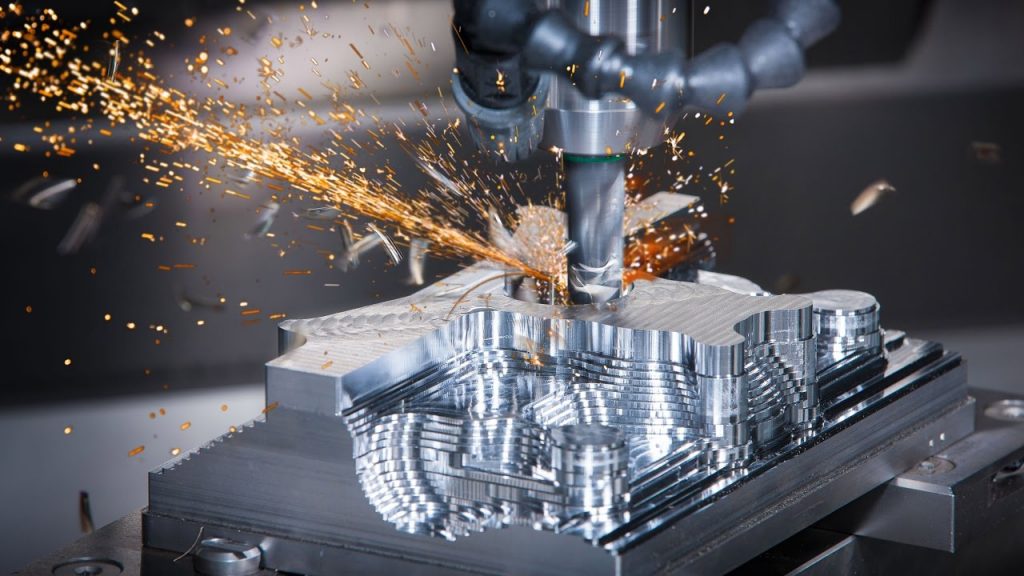
CNC MachiningCNC Machining provides highest tolerance of all technologies because of the way machines are operated. In CNC Machining process, material is cut from the block to get the required shape. In CNC Machining, a gantry is present that moves to the exact location and chips away the material. Since the machine movement is gantry based, the material shall be removed to the exact tolerance.

3D PrintingIn 3D Printing, parts are manufactured through deposition of material. In 3D Printing, laser / infrared light / heated nozzle are used to add material layer by layer and create the final part. As 3D Printing is additive in nature where material is melted and fused, the tolerances achieved in 3D Printing aren’t as high as those achieved in CNC Machining. SLA technology offers the best resolution of all technologies. FDM offers the lowest resolution. Typical tolerance varies from 10 micron to 100 micron.

Sheet Metal: Sheet  Metal provides the lowest tolerance of all because of the very nature of part production in sheet metal fabrication. Sheet Metal Fabrication involves bending the metal parts to achieve the desired shape. When bending the metal parts, the expansion / contraction of the part depends on the metal and tool in use and their respective tolerances. The part behavior varies depending on where the part is bent. If the part is bent closer to the edge, it expands at a different rate than when the part is bent far from the edge. In sheet metal fabrication, the tolerance on the surface is lot higher than the tolerance on the bent part.

To summarize the discussion, CNC Machining provides the best tolerance of these 3 technologies, then comes 3D Printing and finally sheet metal fabrication.


Categories
Latest News

3D Printing, A Detailed Guide

3D Printing has been quoted as potentially being larger than the internet. Some believe it is true while others believe this is part of the extraordinary hype that exists around this technology. So, what is 3D Printing, who uses 3D Printers and what for? Read on to learn more about this amazing technology.

3D Printing Basics

Overview

3D Printing is an umbrella terms comprising a host of processes and technologies that offer a full spectrum of capabilities to produce parts and products in different materials. Essentially, what these processes and technologies have in common is the way production is carried out layer by layer in an additive process which contrasts with the traditional methods of production involving subtractive methods or molding/casting processes. This overview article aims to provide audience with reliable background on 3D Printing in terms of what it is, its history, application areas and benefits.

What is 3D Printing?

3D Printing is a process for making a physical object from a three-dimensional digital model, typically by laying down many successive thin layers of a material. It brings a digital object (its CAD representation) into its physical form by adding layer by layer of materials. 3D Printing brings two fundamental innovations: the manipulation of objects in their digital format and the manufacturing of new shapes by addition of material. The fundamental differentiating principle behind 3D Printing is that it is an additive manufacturing process. Components are made by adding material layer by layer. Thus this technology is radically different from other manufacturing technologies that are subtractive in nature where parts are made by removing material from existing block.

Traditional manufacturing has lot of limitations. Traditional manufacturing demand subtracting material from a larger block whether to achieve the end product itself or to a produce a tool for casting or molding processes and this is a serious limitation within the overall manufacturing process. For many applications traditional design and production processes impose a number of unacceptable constraints, including the expensive tooling, fixtures, and the need for assembly for complex parts. In addition, the subtractive manufacturing processes can result in up to 90% of the original block of material being wasted. In contrast, 3D printing is a process for creating objects directly, by adding material layer by layer in a variety of ways, depending on the technology used.

3D printing is thus an enabling technology providing unprecedented design freedom while being a tool-less process that reduces prohibitive costs and lead times. Components can be designed specifically to avoid assembly requirements with intricate geometry and complex features created at no extra cost. 3D printing is also emerging as an energy-efficient technology that can provide environmental efficiencies in terms of both the manufacturing process itself, utilizing up to 90% of standard materials, and throughout the products operating life, through lighter and stronger design.

In recent years, 3D printing has graduated from being an industrial prototyping and manufacturing process as the technology has become more accessible to small companies. Previously only huge multi national corporations used to own 3D Printers due to the scale and economics of owning a 3D printer but now many smaller 3D printers can now be acquired for under $1000. This has opened up the technology to a much wider audience, and as the exponential adoption rate continues apace on all fronts, more and more systems, materials, applications, services and ancillaries are emerging.

History of 3D Printing

The earliest 3D printing technologies first became visible in the late 1980’s at which time they were called Rapid Prototyping (RP) technologies. This is because the processes were originally conceived as a fast and more cost-effective method for creating prototypes for product development within industry. The origins of 3D printing can be traced back to 1986, when the first patent was issued for stereolithography apparatus (SLA). This patent belonged to one Charles (Chuck) Hull, who first invented his SLA machine in 1983. Hull went on to co-found 3D Systems Corporation — one of the largest and most prolific organizations operating in the 3D printing sector today.

3D Systems’ first commercial RP system, the SLA-1, was introduced in 1987 and following rigorous testing the first of these systems was sold in 1988. In 1987, Carl Deckard, who was working at the University of Texas, filed a patent in the US for the Selective Laser Sintering (SLS) RP process. This patent was issued in 1989 and SLS was later licensed to DTM Inc, which was later acquired by 3D Systems. In 1989, Scott Crump, a co-founder of Stratasys Inc. filed a patent for Fused Deposition Modelling (FDM) — the proprietary technology that is still held by the company today, but is also the process used by many of the entry-level machines, based on the open source RepRap model, that are prolific today. In Europe, 1989 also saw the formation of EOS GmbH in Germany, founded by Hans Langer with a greater focus on the laser sintering (LS) process. Today, the EOS systems are recognized around the world for their quality output for industrial prototyping and production applications of 3D printing. The company’s direct metal laser sintering (DMLS) process resulted from an initial project with a division of Electrolux Finland, which was later acquired by EOS.

Multiple other 3D printing technologies and processes were also emerging during these years, namely Ballistic Particle Manufacturing (BPM), Laminated Object Manufacturing (LOM), Solid Ground Curing (SGC) and ‘three dimensional printing’ (3DP). And so the early nineties witnessed a growing number of competing companies in the RP market but only three of the originals remain today — 3D Systems, EOS and Stratasys.

Throughout the 1990’s and early 2000’s a host of new technologies continued to be introduced still focused on industrial applications and while they were still largely processes for prototyping applications, R&D was also being conducted by the more advanced technology providers or specific tooling, casting and direct manufacturing applications. This saw the emergence of new terminology, named Rapid Tooling (RT), Rapid Casting (RC), Rapid Manufacturing (RM) respectively.

When it comes to commercial operations, Sanders Prototype and ZCorporation were set-up in 1996 Arcam was established in 1997, Objet Geometries launched in 1998, MCP Technologies introduced the SLM technology in 2000, EnvisionTec was founded in 2002, ExOne was established in 2005 and Sciaky Inc was pioneering its own additive process based on its proprietary electron beam welding technology. During the mid-nineties the sector started to show signs of distinct diversification with two specific areas of emphasis. First, there was the high end of 3D Printing which was geared towards part production for high value, highly engineered, complex parts. At the other end of the spectrum, we have ‘concept modellers’ that kept the focus on improving concept development and functional prototyping. At the lower end of the market, the 3D Printers that today are seen as being in mid range, a price war emerged together with incremental improvements in printing accuracy, speed and materials.

In 2009, the first commercially available low cost 3D Printer in kit form and based on the RepRap concept was offered on sale. This was closely followed by Makerbot industries in April the same year, the founders of which were heavily involved in the development of RepRap until they departed from the Open Source philosophy following extensive investment. In 2012, alternative 3D Printing processes were introduced at the entry level of the market. B9Creator came first in June followed by Form 1 in December. Both were launched via Kickstarter and both enjoyed huge success. 2013 was the year of significant growth and consolidation. One of the most notable moves was the acquisition of Makerbot by Stratasys.

3D Printing Technology

Starting point for any 3D Printing process is a 3D digital model which can be created using a variety of 3D software programs or scanned with a 3D scanner. The model is then ‘sliced’ into layers , thereby converting the design into a file readable by the 3D Printer. The material processed by the 3D Printer is then layered according to the design and the process. As stated, there are a number of different types of 3D Printing technologies, which process different materials in different ways to create the final object. Functional plastics, metals, ceramics and sand are now all routinely used for industrial prototyping and production applications. Research is also being conducted for 3D Printing bio materials and different types of food. At the entry level of the market, materials are much more limited. Plastic is currently the only widely used material, usually ABS or PLA but there are a growing number of alternatives, including Nylon. There is also a growing number of entry level machines that has been adapted for foodstuffs, such as sugar and chocolate.

How it Works

Different 3D printers employ different technologies to process materials. For example, some 3D printers process powdered materials that utilize a light/heat source to sinter layers of the powder together in the defined shape. Others process polymer resin materials and again utilize a light/laser to solidify the resin in ultra thin layers. Jetting of fine droplets is another 3D printing process. But the most common and easily recognized process is deposition, and this is the process employed by majority of entry-level 3D printers. This process extrudes plastics, commonly PLA or ABS, in filament form through a heated extruder to form layers and create the predetermined shape.

As parts can be printed directly, it is possible to produce very detailed and intricate objects, often with functionality built in and negating the need for assembly. Another important point to note is that none of the 3D Printing processes come as plug and play options. There are many steps prior to pressing print and more once the part comes off the printer.

3D Printing Processes

Stereolithography: Stereolithography (SLA) is widely recognized as the first 3D printing process of the various 3D Printing processes present in the market. SLA is a laser-based process that works with photopolymer resins. These resins react with the laser and cure to form very precise and accurate parts. The photopolymer resin is held in a vat with a movable platform inside. A laser beam is directed in the X-Y axes across the surface of the resin according to the 3D data supplied to the machine whereby the resin hardens precisely where the laser hits the surface. Once the layer is completed, the platform within the vat drops down by a fraction and the subsequent layer is traced out by the laser. This continues until the entire object is completed and the platform can be raised out of the vat for removal. Because of the nature of the SLA process, it requires support structures for some parts, specifically those with overhangs or undercuts. These structures need to be manually removed. In terms of other post processing steps, many objects 3D printed using SL need to be cleaned and cured. Curing involves subjecting the part to intense light in an oven-like machine to fully harden the resin. Stereolithography is generally accepted as the most accurate 3D printing processes with excellent surface finish. However certain limiting factors include the post-processing steps required and the stability of the materials over time, which can become more brittle.

Digital Light Processing: Digital Light Processing (DLP) process is very similar to that of stereolithography in that it is a 3D printing process that works with photopolymers. The major difference between SLA & DLP is the light source. DLP uses a more conventional light source, such as an arc lamp, with a liquid crystal display panel or a deformable mirror device (DMD), which is applied to the entire surface of the vat of photopolymer resin in a single pass, generally making it faster than SLA. Also like SLA, DLP produces highly accurate parts with excellent resolution, but its similarities also include the same requirements for support structures and post-curing. One key advantage of DLP over SLA is that only a shallow vat of resin is required to facilitate the process, which generally results in less waste and lower running costs.

Laser Sintering / Laser MeltingLaser sintering and laser melting are interchangeable terms that refer to a laser based 3D printing process that works with powdered materials. The laser is traced across a powder bed of tightly compacted powdered material in the X-Y axes. As the laser interacts with the surface of the powdered material it sinters, or fuses, the particles to each other forming a solid. As each layer is completed the powder bed drops incrementally and a roller smoothens the powder over the surface of the bed prior to the next pass of the laser for the subsequent layer to be formed and fused with the previous layer.

The build chamber is completely sealed to maintain a precise temperature during the process. Once printing is finished, the entire powder bed is removed from the machine and the excess powder is removed to leave the ‘printed’ parts. One of the key advantages of this process is that the powder bed serves as an in-process support structure for overhangs and undercuts, and therefore complex shapes that could not be manufactured in any other way are possible with this process. However, on the downside, because of the high temperatures required for laser sintering, cooling times can be considerable. Furthermore, porosity has been an historical issue with this process, and while there have been significant improvements towards fully dense parts, some applications still necessitate infiltration with another material to improve mechanical characteristics.

Laser sintering can process plastic and metal materials, although metal sintering does require a much higher powered laser and higher in-process temperatures. Parts produced with this process are much stronger than those manufactured with SLA or DLP processes, although the surface finish and accuracy is not as good.

Extrusion / FDM / FFF: 3D printing utilizing the extrusion of thermoplastic material is the most common 3DP process. The most popular name for the process is Fused Deposition Modelling (FDM). The process works by melting plastic filament that is deposited, via a heated extruder, a layer at a time, onto a build platform according to the 3D data supplied to the printer. Each layer hardens as it is deposited and bonds to the previous layer.

FDM processes require support structures for any applications with overhanging geometries. For Fused Deposition Modeling, this entails a second water-soluble material which allows support structures to be relatively easily washed away once the print is complete. Alternately, breakaway support materials are also possible which can be removed by manually snapping them off the part. Support structures have generally been a limitation for entry level FFF 3D Printers. However, as the systems has evolved and improved to incorporate dual extrusion heads, it has become less of an issue.

Binder Jetting:  In Binder Jetting process, binder is jetted and is selectively sprayed into a powder bed of the part material to fuse it one layer at a time to create the required part. Once the layer is completed, the powder bed drops incrementally and a roller smoothens the powder over the surface of the bed prior to the next pass of the jet heads with the binder for the subsequent layer to be formed and fused with the previous layer.

Binder jetting has multiple advantages like the need for support is negated because the powder bed itself provides the functionality. Moreover, a range of different materials can be used like ceramics and food. Another distinctive advantage of the process is the ability to easily add full color palette which can be added to the binder.

The parts thus coming out of the machine aren’t as strong as with the sintering process and thus require post-processing to ensure durability.

Material Jetting: In Material Jetting process the actual build materials are selectively jetted through multiple jet heads. However, the material tend to be liquid photopolymers which are cured with a pass of UV light as each layer is deposited.

Material Jetting process allows for simultaneous deposition of a range of materials which means a single part can be produced from multiple materials with different characteristics and properties. Material Jetting is a very precise 3D Printing method producing accurate parts with very smooth finish.

Selective Deposition Lamination: SDL is a proprietary 3D Printing process developed by MCor technologies. SDL 3D Printing process builds parts layer by layer using standard copier paper. Each new layer is fixed to the previous layer using an adhesive which is applied selectively according to the 3D data supplied to the machine. This means a much higher density of adhesive is deposited in the area that shall become a part and much lower density of adhesive is deposited in the surrounding area that will serve as the support ensuring easy support removal.

Electron Beam Melting: Electron Beam Melting technique is a proprietary process developed by Swedish company ARCAM. This process is very similar to the Direct Metal Laser Sintering (DMLS) process in terms of the formation of parts from metal powder. Key difference here is the heat source which is an electron beam instead of a laser. EBM has the capability of creating full dense parts in a variety of metal alloys and as a result the technique has been particularly successful for a range of production applications in the medical industry. However other sectors such as aerospace and automotive also look into EBM technology for manufacturing fulfilment.

3D Printing Materials:

While the total available materials for 3D Printing is limited when compared to other manufacturing technologies, the range of materials has come a long way from the early days of 3D Printing. Now we have a wide variety of materials of different types that are supplied in different forms, namely powder, filament, pellets, granules, resin, etc. Specific materials are now generally developed for specific platforms performing dedicated applications with material properties that more suit the application.

Nylon or Polyamide is commonly used in powder form with the sintering process or in filament form with the FDM process. It is a strong, flexible and durable plastic material that has proved reliable for 3D Printing. It is naturally white in color but can be colored pre or post printing. This material can also be combined with powdered aluminum to produce another common 3D Printing material for sintering – Alumide.

ABS is another common plastic used for 3D Printing. This material is widely used in entry level FDM 3D printers in filament form. It is a particularly strong plastic and comes in a wide range of colors. ABS can be bought in filament form from a number of non-proprietary sources.

PLA is a bio-degradable plastic material that has gained traction with 3D Printing. It is mainly used in filament form for the FDM process. This material is offered in variety of colors, including transparent which has proven to be  an useful option for some applications of 3D Printing. However, this material is not as durable or as flexible as ABS material. Laywood is specially developed 3D Printing material for entry level extrusion 3D Printers. This material comes in filament form and is a wood/polymer composite.

A growing number of metal and metal derivates are being used for industrial 3D printing. Two of the most common are aluminum and cobalt derivates. One of the strongest and most commonly used metals for 3D Printing is Stainless Steel in powder form for the sintering/melting/EBM processes. The  material is naturally silver but can be plated with other materials to give a gold or bronze effect.

Titanium is one of the strongest possible metal materials and has been used for 3D Printing industrial applications. Supplied in powder form, this material can be used for the sintering/melting/EBM processes.

Ceramics is another material set that can be used for 3D Printing with varying degree of success. Important thing to note with these materials is that post printing the ceramic parts need to undergo the same processes as any ceramic part made using traditional methods of production.

Paper is a 3D Printing material employed by SDL process supplied by Mcor technologies.

There is a huge amount of research being conducted into the potential of 3D Printing biomaterials for a host of medical applications. Living tissue is being investigated at a leading number of institutions with a view of developing applications that include printing human organs for transplant, as well as external tissues for replacement body parts. Other research in this area is focused on developing food stuffs.

Experiments with extruders for 3D Printing food substance has increased dramatically over the last couple of years. Chocolate is the most common one. There are printers that work with sugar, pasta and meat. Research is being undertaken to utilize 3D Printing to produce finely balanced whole meals.

3D Printing Global Effects: 3D Printing is already having an effect on the way products are manufactured. The very nature of this technology permits new ways of thinking in terms of social, economic, environmental and security implications of the manufacturing process with universally favorable results. One of the key factors enabling this is 3D Printing has the potential to bring production closer to end user thereby reducing the current supply chain restrictions. The customization value of 3D Printing and the ability to produce small production batches on demand is a sure way to engage consumers and reduce or negate inventories and stock piling.

Shipping spare parts and products from one part of the world to the other could become obsolete as the spare parts shall be 3D Printed on site. This shall have a major impact on large and small businesses operate and interact on a global scale in future. The ultimate aim for many is for consumers to operate their own 3D Printers at home whereby digital designs of any product are available for download and can be sent to the printer.

The wider adoption of 3D Printing will likely cause re-invention of a number of already invented products and an even bigger number of completely new products. Previously impossible shapes and geometries can now be created using 3D Printer. 3D Printing is believed by many to have great potential to inject growth into innovation and bring back local manufacturing.

3D Printing Benefits & Value: 

(a) Customization: 3D Printing process allows for mass customization. The nature of 3D Printing means within the same build chamber numerous products can be manufactured at the same time according to end user requirement at no additional process cost.

(b) Complexity: Advent of 3D Printing has seen a proliferation of products which involve levels of complexity that couldn’t be produced physically in any other way. This made a significant impact on industrial applications, whereby applications are being developed to materialize complex components that are proving to be both lighter and stronger than their predecessors. Notable uses are emerging in aerospace sector where these issues are of primary importance.

(c) Tool-less: For industrial manufacturing, production of the tools is the most complex, cost, time & labor intensive. For low to medium volume applications, industrial 3D Printing can eliminate the need for tool production and thus the costs, lead times and labor associated with it. This is an extremely attractive proposition that an increasing number of manufacturers are taking advantage of. Because of the complexity advantages stated above, products and components can be designed specifically to avoid assembly requirements with intricate geometry and complex features further eliminating the labor and costs associated with assembly processes.

(d) Environment Friendly: 3D Printing is also emerging as energy efficient technology that can provide environmental efficiencies in terms of both the manufacturing process itself utilizing up to 90% of standard materials but also throughout an additively manufactured product’s operating life by way of lighter and stronger design that imposes a reduced carbon footprint compared to traditionally manufactured products.

3D Printing Applications: The origins of 3D Printing were founded on the principles of industrial prototyping as a means of speeding up the earliest stages of product development with a quick and straightforward way of producing prototypes that allows for multiple iterations of product to arrive more quickly and efficiently at an optimum solution. This saves time and money at the outset of the entire product development process and ensures confidence ahead of production tooling.

Prototyping is still the largest application of 3D Printing today. The developments and improvements of the processes and the materials since the emergence of 3D Printing for prototyping saw the processes being taken up for applications further down the product development process chain. Tooling and casting applications were developed utilizing the advantages of different processes. Again, these applications are increasingly being used and adopted across industrial sectors.

Similarly for final manufacturing operations, the improvements facilitate uptake. In terms of industrial vertical markets that are benefitting greatly from industrial 3D Printing across all of these broad spectrum applications.

Medical & Dental: Medical sector is viewed as one of the early adopters of 3D Printing and also a sector with huge growth potential due to customization and personalization capabilities of the technologies and the ability to improve people’s lives as the processes improve and materials are developed that meet medical grade standards.

Aerospace: The aerospace sector was an early adopter of 3D Printing technologies in their earliest forms for product development and prototyping. Because of the critical nature of aircraft development, the R&D is demanding & strenuous, standards critical and industrial grade 3D Printing machines are put through their paces. Process and materials development have seen a number of key applications developed for the aerospace sector. High profile users include GE / Morris Technologies, Airbus/EADS, Rolls-Royce, BAE Systems and Boeing. While most of these companies do take a realistic approach in terms of what they are doing now with the technologies and most of it is R&D, some do get quite bullish about the future.

Automotive: Automotive is another great early adopter of Rapid Prototyping technologies. Many automotive companies, particularly at the cutting edge of motor sport & F1 have followed a similar trajectory to the aerospace companies. First using the technologies for prototyping applications but developing and adapting their manufacturing processes to incorporate the benefits of improved materials and end results for automotive parts.

Many automotive companies are now also looking at the potential of 3D Printing to fulfill their after-sales functions in terms of production of spare / replacement parts on demand rather than holding huge inventories.

Jewellery: Design and manufacturing process for jewellery has always required high levels of expertise and knowledge involving specific disciplines that include fabrication, mould-making, casting, electroplating, forging, silver/gold smithing, stone-cutting, engraving and polishing. Each of these disciplines have evolved over years and each requires technical knowledge when applied to jewelry manufacture. For Jewelry sector, 3D Printing has proved to be particularly disruptive. There is a great deal of interest based on how 3D Printing can contribute to the further development of this industry. From new design freedoms enabled by 3D CAD and 3D Printing through improving traditional processes for jewellery production all the way to direct 3D Printed production eliminating many of the traditional steps, 3D Printing continues to have a tremendous impact on this sector.

Art, Design & Sculpture: Artists and sculptors are engaging with 3D Printing in multiple ways to explore form & function in ways that aren’t possible previously. Whether purely to find new original expression or to learn from old masters this is a highly charged sector that is increasingly finding ways of working with 3D Printing and introducing the results to the world. There are a numerous artists that have now made a name for themselves by working specifically with 3D Modelling, 3D Scanning & 3D Printing technologies.

Architecture: Architecture models have long been a regular application of 3D Printing processes for providing accurate demonstration of an architect’s vision. 3D Printing offers a relatively fast, easy and economically viable method of producing detailed models directly from 3D CAD, BIM or other digital data that architects use. Many successful architectural firms now use 3D Printing as a critical part of their workflow for increased innovation and improved communication.

Fashion: As 3D Printing processes have improved in terms of resolution and more flexible materials, one industry has come to the fore. 3D Printed accessories including shoes, head-pieces, hats and bags have all made their way on to global cat-walks. Some even more visionary fashion designers have demonstrated the capabilities of the tech for haute couture.

Food: Food is another emerging application of 3D Printing that has the potential to truly take the technology into mainstream. Initial forays into 3D Printing food were with chocolate and sugar and these developments have continued apace with specific 3D Printers hitting the market. Some other early experiments with food include the 3D Printing of meat at the cellular protein level.

Consumers: The holy grail of 3D printing vendors is consumer 3D Printing. Currently, consumer uptake is low due to the accessibility issues that exist with entry level 3D Printers. There is a headway being made in this direction by the larger 3D Printing companies such as 3D Systems and Makerbot. There are currently three main ways that the person on the street can with 3D Printing tech for consumer products.

In total, 3D Printing is going to change the way products are manufactured. 3D Printing doesn’t even contribute 1% of the overall manufacturing and has lot of scope for growth in days to come.

Categories
Latest News Learning Center

What is heat treatment and how does it improve CNC machined parts?

Heat treatment is the process of heating or chilling, normally to extreme temperatures to achieve desired result such as hardening or softening of the material. Different types of heat treatment affect CNC machined parts differently. In the below section, we shall explain how heat treatment can significantly enhance the alloy’s fundamental properties, including machinability, strength and hardness.

What does heat treatment do in CNC machining?

Heat treatment is an integral stage in CNC machining. Heat treatment in CNC machining includes the measured heating and cooling of the metal or other materials to attain the desired properties.

This heating process involves the alteration of four primary properties of the metal parts, including:

  • Strength
  • Hardness
  • Ductility
  • Toughness

However, it is true that not all the treatments for the various metal parts are equal.

One can quickly choose the ideal heat treatment depending on the composition of the material, part size, and desired final metal properties.

The primary purpose of performing this heat treatment in CNC machining is to attain the specific microstructure, which provides the parts with particular material properties.

When should this heat treatment be applied to the metal parts?

The heat treatment can be applied at several stages of the entire CNC machining process. This can be done before starting with the machining of parts after doing so.

  • Heat treatment before CNC machining

When a metal alloy with a standardised grade is requested, which is also readily available in that case, the service provider will machine the metal parts directly from the material.

  • Heat treatment after CNC machining

Several heat treatments may drastically enhance the material’s hardness and use it as a final step after forming. In such a case, heat treatment is applied after the CNC machining because the higher hardness diminishes the material’s machinability.

Common heat treatments and enhancements it does.

  • Annealing, tempering, and stress relieving.

This type of heat treatment involves the metal alloys heating to a higher temperature and then cooling at a slower rate. Annealing is generally applied to all the alloys, and before any further processing, these alloys are softened and enhanced in their machinability.

Tempering heats the alloy part at a lower temperature than annealing and is generally employed after performing the alloy steel and mild steel’s quenching. This helps in enhancing mechanical performance and diminishes brittleness.

Stress relieving includes the specific part’s heating to a higher temperature but lower as compared to annealing. This is generally done after the CNC machining process in order to remove the residual stress generated due to the manufacturing process.

  • Quenching

The quenching process includes the metal’s heating at a higher temperature followed by a swift cooling step by sipping the whole material in water or oil or exposing it to some cool air. The rapid cooling of the metal locks in the modifications in microstructure such that the metal experiences heat when heated up, resulting in materials with a higher hardness.

  • Aging or Precipitation hardening

Aging or precipitation hardening includes a three-step process where the material is heated first to a higher temperature, then quenched, and later heated to a lower temperature for a longer term.

This makes the alloy elements appear as different particles of varied compositions to distribute and dissolve perfectly, like sugar dissolves in water when heated. After performing the precipitation hardening process, the metal alloy’s hardness and strength enhance drastically.

  • Carburizing and Case Hardening

The case hardening process results in the metal parts remaining with higher hardness, whereas the underlying materials remain soft. It is a standard heat treatment of metals that includes mild heating steel into a carbon-rich environment and follows the quenching process to lock the carbon into a metal material matrix, enhancing the surface hardness.

Bottom Line!

Each heat treatment for a specific metal enhances its hardness and some other properties that a professional might only help with to understand and diagnose which one could help!

Think3D understands the technical know-how and delivers the best properties any metal can!

Categories
Learning Center

How to design parts for CNC machining

Designing parts of CNC machining requires few easy steps. One can explore the broad capabilities of CNC machining by following some design for manufacturing rules. And since no industry-specific standards exist, attaining this can be highly challenging. Although there are no industry-specific standards, we have compiled several best practices for CNC machining here. Read on to acquire comprehensive information on this!

CNC machining design guidelines!

CNC machining and tool manufacturers consistently enhance their technological capabilities and extend their ability to explore the new and innovative methods possible. Here the below-mentioned information and values for common featured CNC machinery parts can sum up the standard guidelines, following which can be beneficial.

Pockets and Cavities

Ample end mills tools have a specific cutting length that is generally 3 to 4 times their diameter. However, limiting this cavity depth to 4 times can ensure more satisfactory outcomes. And the chip evacuation, vibrations, and tool deflection has become more prominent when the cavities include a reduced depth-to-width ratio.

Therefore, the recommended cavity depth is four times the overall cavity width.

Deep Cavities milling

Cavities having higher depth greater than six times the tool diameter, are often considered deep.

Internal edges

1 . Vertical Corner radius

Utilizing the recommended internal corner radii values ensures that a specific diameter tool can be used and aligns well with the recommended guidelines for desired cavity depth. Therefore, the recommended vertical corner radius is 1/3 times the depth of the cavity.

2. Floor Radius

The mill tools have a slightly rounded or a flat lower cutting edge, and to get the desired outcomes, it is always good to follow the best practices to utilize the recommended values. The recommended floor radius is 1 mm or 0.5 mm, or no radius.

Thin walls

The decreased wall thickness diminishes the material stiffness, which leads to enhanced vibrations during CNC machining while lowering the attainable accuracy.

Therefore, the recommended thin wall specifications include 0.8 mm for metals and 1.5 mm for plastic which is feasible for 0.5 mm and 1.0 mm, respectively.

Holes

1. Diameter

Holes are made using an end mill tool or a drill bit. The drill bits size is standardized, while to attain the higher accuracy homes, a diameter lesser than 20 mm is recommended. This is with the standard diameter holes.

2. Maximum depth

For non-standardized diameter holes, machining with an end mill tool is required. In such cases, the maximum cavity limitations are applied, and the recommended maximum depth value is required to be utilized.

Therefore, the recommended maximum depth is four times the nominal diameter; the typical value is ten times the nominal diameter, and the feasible one is 40 times.

Thread

1. Thread size

Threads are cut with the taps with a minimum M1 size, and the recommended size for the thread sizing is M6 or larger.

2. Thread Length

Most of the load is applied to the threat, so the minimum thread length is 1.5 times the nominal diameter, while the recommended one is three times the nominal diameter.

Small features

The recommended minimum hole diameter is 2.5 mm, whereas the feasible value is 0.05 mm.

Tolerance

Tolerance generally defines the specific boundaries for an acceptable dimension. The typical attainable tolerance value is +- 0.1 mm, and the feasible one is +- 0.02 mm.

Texting and Lettering

The engraved text type is preferred over the embossed one as doing so requires less material removal. So, the recommended font size is 20 or larger with 5mm engraved text.

Bottom Line!

Following the above-mentioned best practices and information can helpfully attain the desired outcomes. THINK3D has compiled the best information and follows the same to achieve excellence in CNC machining.

Categories
Latest News Learning Center

How 3D Printing is Disrupting the Making of Footwear

How 3D Printing is Disrupting the Making of Footwear

Footwear industry is a unique industry that demands extensive research for newer, tougher and light weight materials for manufacturing new and premium shoes. Big footwear brands like Adidas and Nike are taking 3D printing to the very edge by directly collaborating with 3D printing companies like EOS, Formlabs and 3D systems to develop performance, sports wear shoes.

Materials

Using right materials that suit the manufacturing requirement for the shoes is key. Elastic Polyurethane based materials and flexible TPU are the most preferred materials for manufacturing shoes. These materials are used to make shoe mid soles or the upper parts of the shoe.

Speed

It is important that the 3D printing process is also faster for mass production. Hence companies have also working closely towards achieving a faster printing rate. For example, Carbon, a 3D printer manufacturing company has come up with Digital Light Synthesis to cure photosensitive resins quicker.

Geometry

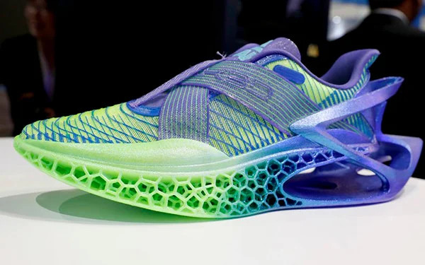
Being able to bear the load of the person and also being light in weight poses a design challenge. But with 3D printing, complex lattice structures can be manufactured. Adidas unveils Futurecraft 4D, which is the world’s first mass-produced 3D printed shoe. The shoe’s midsoles have a unique lattice structure that is light weight, durable and is completely resin printed.

Customization

3D printing helps the footwear and fashion designers to quickly generate concepts and evaluate them. Nike which is one of the top brands experimented by conducting a 3D printing workshop that allows customers to customize their shoes and then place the order. ECCO also announced that it is launching a similar system and it partnered with Dassault Systems for developing the tool that allows customers to choose their designs among pre-modeled combinations.

Share This Story, Choose Your Platform!

Facebook

Twitter

LinkedIn