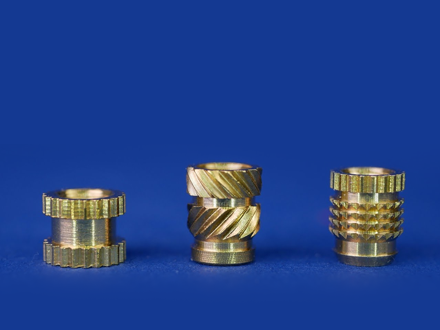
Many functional 3D printed prototypes have various parts that need to be fastened with screws. In order to test the prototype in the actual usage conditions there should be a way to fasten the 3D printed parts with screws. Modeling the screw threads and printing them as-is is proved to be not strong enough to hold the screws. This problem can be solved with heat set inserts (threaded inserts). These heat set inserts come in various standard thread sizes for M2, M3, M5 etc. These threaded inserts have shown to have really good strength to retain the fastening screw and the parts that are being held with the screw joint. Let’s have a more detailed look on the design considerations and installation guide for heat set threaded inserts.
Boss Hole Size
It is generally a trial and error method to determine the perfect hole size that is not too large for the insert to become loose nor too small that makes it difficult to melt a lot of material. A general guide is to design the boss hole to be 0.4 mm smaller in diameter than the outer diameter of the insert being used. For example if the insert outer diameter is 4.2 mm, design the insert hole to be 3.8 mm in diameter and the interference of 0.2 mm would be generally enough for a perfect and tight lockage once the insert is heated and fixed and part is cooled.
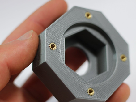
(a) Perimeters or Walls around the boss
If the part is to be printed in FDM machines, it is recommended that at least 3 to 4 perimeters or walls are given in the slicing software around the holes so that the insert will have enough material to melt and bond together firmly to give more strength. Also it is recommended to print the part in 100% infill or as high infill as possible. In a situation where part is large and 100% infill is not feasible, try to increase the wall thickness in the design and like mentioned earlier, wall line count (or perimeters depending on the slicer terms) has to be high 3+. If the part is printed in any other technology printers, it is recommended that there is at least 2.5 mm of material surrounding the insert boss hole.
(b) Effectiveness of heat set inserts
Heat set inserts can greatly improve both the pull-out and torque resistance of fasteners screwed into your printed parts. The exact effectiveness of the insert is dependent on a number of factors, including the quality of the insert itself, the material used, and the settings used when printing your part. Higher-strength materials like ABS or PETG are generally a better choice when using threaded inserts as weaker materials like PLA can end up becoming the point of failure, rather than the insert. Flexible materials like TPU are less suitable as the plastics’ inherent ability to deform means the insert will not stay in place securely. When choosing your print settings, the best option is to use a high infill percentage with 100% infill being preferred. If the part you plan to use an insert with is large and a high infill percentage is impractical, make sure you’re at least using a high wall count (3+) and consider increasing the thickness of your outer walls.
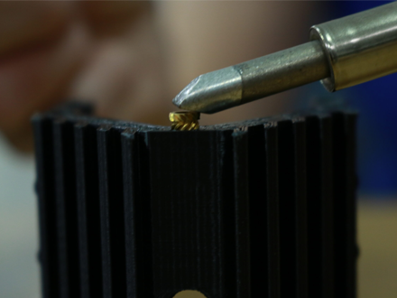
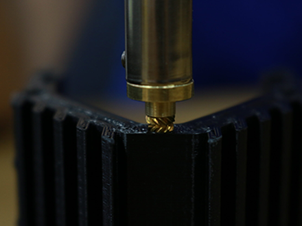
(c) Installation Procedure
Place your insert into the associated hole it will be pushed into. Take your heated soldering iron, place it in the middle of the insert and apply a small amount of pressure making sure not to touch the plastic with the soldering iron directly. As the insert starts heating up you’ll see it sink into the hole. Allow the part to cool. A good practice is to first let the pressure of the hot soldering iron to initially dip the insert into position but not completely through. Once the alignment is satisfied, the insert can be further pushed vertically so that the insert is perfectly vertical otherwise the screw does not go through the threads
© Copyright 2014 – 24 THINK3D. All rights reserved