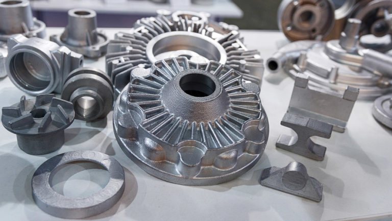
Pressure die casting is a quick, reliable and cost-effective manufacturing process for production of high volume metal components that have tight tolerances. Basically, the pressure die casting process involves injecting molten metal alloy into a steel mold under high pressure. Common problem with pressure die casting is porosity. Let’s understand what is it and how to control it.
What is porosity?
Porosity is the presence of small voids, holes or pockets of air trapped within metal. These pores can be in the form of fine cracks or tiny cylindrical holes. Typically, porosity occurs when air is trapped into the metal by the die casting machinery, often leaving gaps at the top of the die or when some early solidification happens preventing the liquid metal to completely fill the cavity.
Causes Of Porosity:
There are 2 major causes of porosity. (a) Gas Porosity (b) Solidification Shrinkage.
a. Gas Porosity
Gas porosity occurs when the metal traps gas (most often nitrogen, oxygen or hydrogen) during casting. When the casting cools and solidifies, bubbles form because the solid form of the metal cannot hold as much gas as the liquid form. These bubbles appear on a casting as rounded, circular cavities or holes.
b. Solidification Shrinkage
As molten metal cools, shrinkage occurs in three distinct stages:
• Liquid Shrinkage is the contraction that occurs as the alloy cools but remains in its liquid state. This is not normally significant from a casting design perspective.
• Liquid-to-Solid Shrinkage (also known as solidification shrinkage) occurs as the alloy changes from liquid to solid. This is significant for the designer as it gives rise to the need to keep fluid metal channels open throughout the mold during cooling as contraction will draw more metal into the casting from the risers.
• Solid Shrinkage is the continued shrinkage that occurs as the solid metal casting cools to ambient temperature in its solid state. This is also significant from the designer’s point of view. It is known as “Patternmaker’s Shrinkage” and must be compensated for within the tooling or mold design to ensure that the specified final overall dimensions are achieved.
Types Of Porosity:
There are 3 types of porosity – (a) Blind Porosity (b) Through Porosity (c) Fully Enclosed Porosity.
a. Blind Porosity
The pore starts at the surface of a feature and ends somewhere within the body of the metal. These types don’t usually affect mechanical strength but they may invite corrosion. It’s possible to seal these pores after casting, especially if the part needs to hold pressure such as in a hydraulic cylinder.
b. Through Porosity
The pore starts at the surface and creates a channel all the way through the feature and out the opposite wall. This causes a leak and would need to be sealed from both sides.
c. Fully Enclosed Porosity
These pores exist within the body of the metal and are not exposed to the outside unless they are later penetrated during post-machining. The existence of such pores is normally not apparent unless the part is subject to a computed tomography (CT) scan after casting or the part is cut open for diagnostic reasons.
Diagnostic Tools For Porosity Analysis
Software like Avizo software for advanced porous materials now exists to help product designers and manufacturers to predict where porosity is most likely to occur. Using this information, product engineers can improve their mold designs accordingly, while molders can also optimize their set-ups in advance rather than rely on costly and time-consuming trial and error.
Tool Design Tips For Porosity Prevention
There are some tool design practices that should be employed to help prevent the most common causes of porosity.
Wall Thickness
Problem: Unequal cooling is the main problem causing for porous formation in the pressure die casting.
Solution: The easiest way to prevent this is to maintain consistent wall thicknesses whenever possible. That is the job of the mold tool designer to look after important considerations such as the design of bosses, ribs, gussets and other features.
Shrink Rate
Problem: The shrink rate is affected by the melting temperature of the alloy, the cooling time and the cooling temp.
Solution: The best that the product developer works closely with the pressure die caster is to discuss options for raw materials based on the application and design.
Entraining
Problem: It is challenging to completely remove entrained air from a mold tool, especially for complex shapes that have many internal features where air can be trapped.
Solution: There are a few strategies for mitigating entrained air. One is to improve the mold tool design so that there are no sharp corners or pockets where air cannot escape. Also, more vents can be added or the design of the gate/runner system optimized to allow escape routes for air. Changing injection speed and pressure may help with venting but can adversely affect the part in other ways so this must be done carefully.
Technology for Measuring Porosity
Various new techniques are being developed to help manufacturers in identifying and in measuring porosity that is very difficult for using conventional methods such as visual inspection, pressure testing or destructive testing. One of the most promising is computed tomography, or CT.
The process includes multiple taking high-powered X-ray photos and then combined with each other to create a 3D map of the inside of the piece. This can be widely used for real-time control as well as for creating computer simulations that can aid in optimizing mold tool designs. CT is becoming robust and reliable enough to qualify as a true metrology-grade measurement instrument and not just a diagnostic tool.
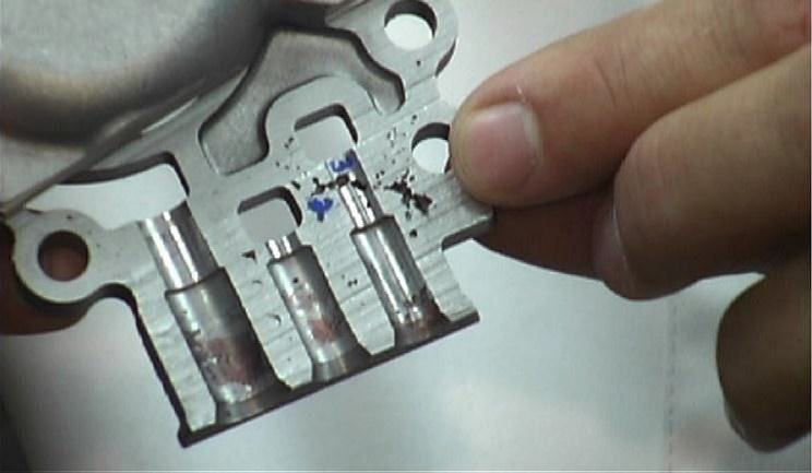
How does machining affect porosity?
The skin of a die cast part is the most thermally stable area and it is the first part to solidify. This shows little or negligible porosity within the first 0.5mm or more because the pores occur in the deeper sections of castings, machining processes like tapped and threaded holes may open enclosed pores. Some of the castings must be able to hold air or liquid pressure, such as for hydraulic cylinders or manifolds, so these pores need to be sealed after machining.
Sealing Pores with Vacuum Impregnation
The process generally consists of three-step as mentioned below.
• The part is placed in a chamber and vacuum is used to remove any trapped air in micro pores.
• A sealant such as a liquid polymer resin is then put into the chamber and forced into the micro pores with positive air pressure.
• Once impregnated, the part is removed from the chamber and the sealant fully cured. This is considered a one-time, permanent surface treatment.
© Copyright 2014 – 24 THINK3D. All rights reserved