One of the design parameter that comes in the way of product design is the part wall thickness as it dictates both structural strength and weight. Although each 3D printing and manufacturing method has its own restrictions on how small the wall thickness can be for achieving the print, it is not the only criteria to decide on the thickness value. Let’s understand it in more detail from 3 perspectives.
1. Printability Limitations in Prototyping phase
From Fused Deposition modeling (FDM) perspective, although the nozzle diameters available are as small as 0.2 mm and it is possible to print walls as thin as 0.2 mm but the problem lies in the layers not sticking properly and also it is very likely that warpage can occur during the print or in the stage where the part is being removed and post processed. Similar problems occur not just in methods but also other technologies. Stereolithography (SLA) can be used to get fine details as small as 0.2 mm but that is not applicable to thin walled parts. To avoid these problems, the least possible wall thickness that can be successfully printed is 0.8 mm. Selective Laser Sintering (SLS) also dictates the thickness to be a minimum of 0.8 mm. Now let’s look at other factors below.
2. Functionality Restrictions
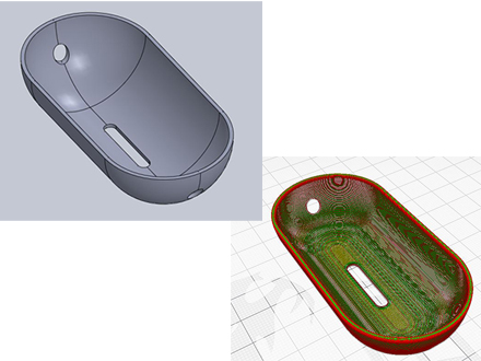
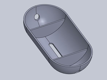
Depending on the application part should have enough strength to withstand the environment, external loads and hold any internal components firmly. It should also not warp due to thermal stresses in the cooling phase in the mold. And if the part has to be light in weight, thicker walls significantly increase the part weight if the part is large. Hence a way to deal with this scenario is to add ribs to the part wherever possible guessing the possible warping and bending modes of the part without increasing the wall thickness. Let’s now look at the production aspects.
3. Production Considerations
Often in the product development process, the aim is not just to achieve the prototypes with 3D printing but to produce parts in small, medium to large batches. Then production techniques like vacuum casting, lost wax casting or injection molding should be used. Each production process has its own restrictions on how small the walls can be. Minimum practical wall thickness for vacuum casting is 2.5 mm for the resin to flow into the mold. Similarly the minimum wall thickness for injection molding to avoid surface defects is 1 mm to 4 mm. The range depends on other design features in the design like bosses, ribs and snap joints which should have sufficient base support strength. And to avoid sink marks on the outer part surface, the ribs should have thickness that is 20% thinner than the base wall. And adding to the above factors, each material also exhibits shrinkage (0.1 to 0.25%) so shrinkage allowance should be given in final mold development.
Best Practices
Once the whole design is completed (adding all internal and external features on the walls) it might not be possible to edit the wall thickness due to CAD software errors. Hence the best practice is to implement parametric design approach for all the features in the design for altering the wall thickness without having to significantly redesign the whole part from scratch. But only downside is that such design formulae should be implemented in the CAD stage right from the beginning. It is important to understand that the new product development is always an iterative process and using 3D printing will help understand the DFM challenges without having to spend huge costs. All in all, starting with a nominal wall thickness of 1.5 mm is always advised as it suits most of the 3D printing, vacuum casting and injection molding methods and any major revisions can be done once the prototyping phase is completed and all functional aspects are met.
© Copyright 2014 – 24 THINK3D. All rights reserved