Categories
Latest News Learning Center

How Polyjet Printing is making Realistic Cosmetic Packaging

How Polyjet Printing is making Realistic Cosmetic Packaging

The cosmetic industry is one that is driven by how the consumers look and feel the packaging before purchase. Although looks is not the only criteria to attract customers, a constant innovation and giving a new look and feel is vital to make them stand out on the shelf. And in most design cases, evaluating each idea purely based on rendered images is not enough and requires prototyping that looks and feels exactly like how the real packaging would be. Thanks to the developments in Polyjet printing, multi-material and multi-coloured prints are possible. Polyjet 3D printing technology uses a print head that sprinkles droplets of photosensitive ink that is cured by the UV light. 

Form

Packaging can be designed in any shape and form due to the fact that 3D printing has no geometric limitations.

Multi-colour

Designs and patterns of different colours can be printed into a single package. This is achieved by the Polyjet print head that selectively deposits the different coloured resins. Blended colours are also possible that transition from one to another along the body.


Text

Text can be directly incorporated into the body instead of engraving or embossing. This is another way to display company logos and product names without having to create embossed text.


Share This Story, Choose Your Platform!

Facebook
Twitter
LinkedIn

Categories
Latest News Learning Center

How 3D Printing is Disrupting the Making of Footwear

How 3D Printing is Disrupting the Making of Footwear

Footwear industry is a unique industry that demands extensive research for newer, tougher and light weight materials for manufacturing new and premium shoes. Big footwear brands like Adidas and Nike are taking 3D printing to the very edge by directly collaborating with 3D printing companies like EOS, Formlabs and 3D systems to develop performance, sports wear shoes.

Materials

Using the right materials that suit for manufacturing the shoes is key. Elastic Polyurethane based materials and flexible TPU that are custom-developed for making shoe mid soles or the upper parts of the shoe are used.

Speed

It is important that the 3D printing process is also faster for mass production. Hence companies have also working closely towards achieving a faster printing rate. For example, Carbon, a 3D printer manufacturing company has come up with Digital Light Synthesis to cure photosensitive resins quicker.

Geometry

Being able to bear the load of the person and also being light in weight poses a design challenge. But with 3D printing, complex lattice structures can be manufactured. Adidas unveils Futurecraft 4D, which is the world’s first mass-produced 3D printed shoe. The shoe’s midsoles have a unique lattice structure that is light weight, durable and is completely resin printed.

Customization

3D printing helps the footwear and fashion designers to quickly generate concepts and evaluate them. Nike which is one of the top brands experimented by conducting a 3D printing workshop that allows customers to customize their shoes and then place the order. ECCO also announced that it is launching a similar system and it partnered with Dassault Systems for developing the tool that allows customers to choose their designs among pre-modeled combinations.

Share This Story, Choose Your Platform!

Facebook
Twitter
LinkedIn

Categories
Latest News Learning Center

The Launch of SINTERIZE Targeting USA Market – THINK3D

THINK3D announces the launch of SINTERIZE targeting USA market

THINK3D, one of India’s largest rapid prototyping facilities offering 3D Printing, CNC Machining, Injection Molding services has today announced the launch of its sister concern SINTERIZE, a USA headquartered digital manufacturing service provider catering to companies from USA & Europe looking to outsource manufacturing work to India.

During the last 2 years, THINK3D experienced increased enquiries and order flow from companies based out of USA & Europe. These enquiries that would otherwise go to manufacturing companies in China. Due to COVID, geopolitical issues and supply chain disruptions many companies started implementing China + 1 strategy for their outsourcing needs. To cater to this change in market dynamics and provide better customer service to clients based in the USA & Europe, THINK3D launched SINTERIZE in the USA. Currently, all orders placed on SINTERIZE website shall be executed by THINK3D in India.

According to Raja Sekhar Upputuri, co-founder & CEO of THINK3D, “We are delighted to launch our service in the USA under the SINTERIZE brand. We got this idea to launch our services in the USA market in late 2019 but with the onslaught of pandemic, our launch plan took a back seat and we shifted our focus towards manufacturing RT-PCR devices, cartridges and SWABs. With things getting back to normal now, we felt the time was right to launch the service. Having a one-stop shop offering 3D Printing, CNC Machining, Injection Molding services all under one roof, we are confident of delivering high quality service to the customers in the USA”.

Currently, all projects received by SINTERIZE shall be executed by THINK3D at its facility in India. Over time, we plan to onboard multiple service providers across S.Asia & S.E. Asia to cater to diverse needs of the customers. We also have plans to install industrial 3D Printers in the USA to cater to growing 3D Printing needs of local customers.

According to Kishore Karlapudi, co-founder & CEO Sinterize, “I have been observing THINK3D over the last 7 years and what they have achieved in the digital manufacturing space in India in such a short span is phenomenal. Given the expertise THINK3D team gained in this space, we felt it natural to partner with them to launch digital manufacturing services in the USA. We also have plans to roll out an online ordering process and a custom ERP to automate the entire end-to-end workflow. Our goal is to reach $100 million in revenue in the next 3-5 years.”

“With a dedicated team of product developers, we helped around 2000 innovators till date translate their ideas into functional products. In many cases, we are also their manufacturing partner for their batch production and mass production needs. With NPD, 3D Scanning, 3D Designing, 3D Printing, CNC Machining, all under one roof, we could provide seamless experience to product innovators and could reduce their time to market drastically.”, added Raja Sekhar Upputuri

Share This Story, Choose Your Platform!

Share on facebook
Facebook
Share on twitter
Twitter
Share on linkedin
LinkedIn

Categories
Latest News Learning Center

How 3D Printing Can Enhance Education in Schools

Heat Set Inserts in 3D Printed Parts: Use, Installation and Benefits

3D Printing has now become more affordable than it was some 10 years ago and desktop sized eco-friendly and child-safe 3D printers are now available at affordable prices. This has opened up a huge potential in teaching with a lot of creative options that not only enhance the knowledge gained by the students but also helps them remember the concepts for a long time. Alongside the traditional ways of teaching on a black board and using a screen to show images and animations, having a way to show 3D models that can be tailored for the concept being taught is a new and creative way. While the possibilities are vast and cannot be covered, these 5 examples demonstrate ways that can act as a root for further opportunities. And softwares like TinkerCAD and open-source design libraries like Thingiverse  have made 3D modeling and 3D printing much easier than traditional 3D modeling softwares that any teacher can learn and print those models with ease.

Volumes and Shapes

3D printed geometric models help for imagining the shape and volume such as cylinder, sphere, cone, pyramids, prisms etc. For example, volume of a sphere and the volume of a cylinder of same dimensions can be mathematically verified by pouring known volumes of water into the 3D printed hollow cylinders and spheres and show how they compare to each other.


Chemical Molecule Structures

Chemical molecules have complex 3-Dimensional structures and 3D printed models can help understand how the molecules are formed from the atoms.


Areas and Angles

3D printed areas and angles help students understand fractions. It is possible to print pie pieces in portions of 1/1, 1/2, 1/3, 1/4, 1/5, 1/6, 1/8, 1/10, 1/12, and 1/16. With these pieces, one can illustrate how to add, subtract and create a whole from the fractions. Also, show equations in a visual way, such as demonstration of portions in the form of 2 quarters equals half and 2 halves equals 1 and so on.


Science Concepts

Some fundamental concepts like center of mass, center of gravity and buoyancy can be made understood with the help of 3D objects. For example, center of mass of a disc and center of mass of an irregular object are different and can be visualized by trying to identify a pin point where the object can be balanced. Also small objects can be placed in water to show why some float and others get submerged.


Monuments and History

3D printed monuments help students appreciate the historical and cultural heritage of the world.


Share This Story, Choose Your Platform!

Share on facebook
Facebook
Share on twitter
Twitter
Share on linkedin
LinkedIn

Categories
Latest News Learning Center

Heat Set Inserts in 3D Printed Parts

Heat Set Inserts in 3D Printed Parts: Use, Installation and Benefits

Many functional 3D printed prototypes have various parts that need to be fastened with screws. In order to test the prototype in the actual usage conditions there should be a way to fasten the 3D printed parts with screws. Modeling the screw threads and printing them as-is is proved to be not strong enough to hold the screws. This problem can be solved with heat set inserts (threaded inserts). These heat set inserts come in various standard thread sizes for M2, M3, M5 etc. These threaded inserts have shown to have really good strength to retain the fastening screw and the parts that are being held with the screw joint. Let’s have a more detailed look on the design considerations and installation guide for heat set threaded inserts.


Boss Hole Size

It is generally a trial and error method to determine the perfect hole size that is not too large for the insert to become loose nor too small that makes it difficult to melt a lot of material. A general guide is to design the boss hole to be 0.4 mm smaller in diameter than the outer diameter of the insert being used. For example if the insert outer diameter is 4.2 mm, design the insert hole to be 3.8 mm in diameter and the interference of 0.2 mm would be generally enough for a perfect and tight lockage once the insert is heated and fixed and part is cooled.

(a) Perimeters or Walls around the boss

If the part is to be printed in FDM machines, it is recommended that at least 3 to 4 perimeters or walls are given in the slicing software around the holes so that the insert will have enough material to melt and bond together firmly to give more strength. Also it is recommended to print the part in 100% infill or as high infill as possible. In a situation where part is large and 100% infill is not feasible, try to increase the wall thickness in the design and like mentioned earlier, wall line count (or perimeters depending on the slicer terms) has to be high 3+. If the part is printed in any other technology printers, it is recommended that there is at least 2.5 mm of material surrounding the insert boss hole.

(b) Effectiveness of heat set inserts

Heat set inserts can greatly improve both the pull-out and torque resistance of fasteners screwed into your printed parts. The exact effectiveness of the insert is dependent on a number of factors, including the quality of the insert itself, the material used, and the settings used when printing your part. Higher-strength materials like ABS or PETG are generally a better choice when using threaded inserts as weaker materials like PLA can end up becoming the point of failure, rather than the insert. Flexible materials like TPU are less suitable as the plastics’ inherent ability to deform means the insert will not stay in place securely. When choosing your print settings, the best option is to use a high infill percentage with 100% infill being preferred. If the part you plan to use an insert with is large and a high infill percentage is impractical, make sure you’re at least using a high wall count (3+) and consider increasing the thickness of your outer walls.

(c) Installation Procedure

Place your insert into the associated hole it will be pushed into. Take your heated soldering iron, place it in the middle of the insert and apply a small amount of pressure making sure not to touch the plastic with the soldering iron directly. As the insert starts heating up you’ll see it sink into the hole. Allow the part to cool. A good practice is to first let the pressure of the hot soldering iron to initially dip the insert into position but not completely through. Once the alignment is satisfied, the insert can be further pushed vertically so that the insert is perfectly vertical otherwise the screw does not go through the threads


Share This Story, Choose Your Platform!

Share on facebook
Facebook
Share on twitter
Twitter
Share on linkedin
LinkedIn

Categories
Latest News Learning Center

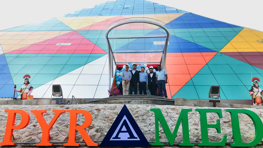
A New Centre of Excellence For 3D Printing Inaugurated At AMTZ

“A

A NEW CENTRE OF EXCELLENCE FOR 3D PRINTING INAUGURATED AT AMTZ

On the occasion of World Health Day, a new building was inaugurated at Andhra Pradesh MedTech Zone Ltd, Visakhapatnam. This building houses the first WHO Collaborating Center For Health Innovation, Indian Society Of Assembly Technologies (I-SAT) & Center Of Excellence For 3D Printing. The building was designed in the shape of Pyramid to reflect the historical and cultural ethos of India and is named “PYRAMED” which reflects the focus on medical devices in particular and the park in general.

The facility inauguration was graced by the presence of various dignitaries like Dr Renu Swarup, Former Secretary, Department of Science And Technology (Virtual); Prof. Vijay Raghavan, Principal Scientific Advisor, GOI (Virtual); Dr Shirshendu Mukherjee, Mission Director, Program Management, BIRAC; J Thoman Vaughan, Director, MR Access, Dr Manish Diwan, BIRAC; Mr Krishna Bandaru, Head Executive Leadership Team, Skill Lync; Dr Arjun Kalyanpur, Founder and CEO, Teleradiology Solutions; Dr Sandeep Chatterjee, Director, Ministry of Electronics and Information Technology, GOI; Rajeev Nath, Forum Coordinator, AIMED; K Manohar Raja, Executive Director, RailTel Corporation Of India; Satish Anantharaman, President, I-SAT, Louis Anersnap, Head, WHO Innovation Hub, WHO-Geneva and Dr Jitender Sharma, MD and CEO.

The 3D Printing Center Of Excellence housed at PYRAMED shall have various innovative 3D Printing technologies namely Ceramic Binder Jetting, SLA 3D Printing, Metal 3D Printing. The mandate of this COE is to  incubate 25 startups, file 10 patents and train 200 students on 3D Printing technology.  Alongside 3D Printing technologies, there are multiple traditional manufacturing technologies like CNC Ultrasonic Welding, Laser Welding technologies in the facility. 

Ms. Lousie Agersnap, Head, WHO Innovation Hub, WHO Geneva speaking on the occasion “I am truly honored to speak at the inauguration of our first WHO center for health innovation at AMTZ in India, what better way to celebrate the World Health Day”. According to Dr. Jitendra Sharma, MD & CEO AMTZ “The whole building is completed in 36 days. The entire team worked really hard 24/7 to finish the building and dedicate it to the country on the occasion of World Health Day”. THINK3D having its presence at the medical park was also a part of the inaugural ceremony among the other dignitaries. “This center of excellence on 3D Printing alongside the existing state of art 3D Printing facility built by THINK3D will make AMTZ a hub of 3D Printing in India. All the major 3D Printing technologies available globally are housed in these 2 facilities within AMTZ. We are hopeful of seeing some innovative startups coming out of this zone soon” says Raja Upputuri, founder and CEO, THINK3D.

PyraMed
PyraMed 3
PyraMed 4
PyraMed 2
PyraMed 5

Previous
Next

About THINK3D: THINK3D is India’s largest integrated 3D Printing service provider offering 3D Scanning, 3D Designing, 3D Printing, CNC Machining, Vacuum Casting, Injection Molding services, all under one roof. Over the last 6 years, we have served various global corporations, academic institutions and hundreds of startups for their 3D Printing needs. Please visit www.think3d.in for all your 3d printing needs. 

About AMTZ: AMTZ is India’s premier medical technology park with Common Manufacturing Facilities & Common Scientific Facilities that include specialized laboratories, warehousing, and testing centers such as the Center for Electromagnetic Compatibility and Safety Testing, Center for Biomaterial Testing, Center for 3-D Printing, Centers for Lasers, MRI Superconducting Magnets, Gamma Irradiation Centre, Mold & Machining Centre, and many other industrial service centers.

Share This Story, Choose Your Platform!

Share on facebook
Facebook
Share on twitter
Twitter
Share on linkedin
LinkedIn

Categories
Latest News Learning Center

Porosity in Pressure Die Casting and How to Control It

Porosity in Pressure Die Casting and How to Control It

Pressure die casting is a quick, reliable and cost-effective manufacturing process for production of high volume metal components that have tight tolerances. Basically, the pressure die casting process involves injecting molten metal alloy into a steel mold under high pressure. Common problem with pressure die casting is porosity. Let’s understand what is it and how to control it.

What is porosity?

Porosity is the presence of small voids, holes or pockets of air trapped within metal. These pores can be in the form of fine cracks or tiny cylindrical holes. Typically, porosity occurs when air is trapped into the metal by the die casting machinery, often leaving gaps at the top of the die or when some early solidification happens preventing the liquid metal to completely fill the cavity.

Causes Of Porosity:

There are 2 major causes of porosity. (a) Gas Porosity (b) Solidification Shrinkage.

a. Gas Porosity

Gas porosity occurs when the metal traps gas (most often nitrogen, oxygen or hydrogen) during casting. When the casting cools and solidifies, bubbles form because the solid form of the metal cannot hold as much gas as the liquid form. These bubbles appear on a casting as rounded, circular cavities or holes.

b. Solidification Shrinkage

As molten metal cools, shrinkage occurs in three distinct stages:

• Liquid Shrinkage is the contraction that occurs as the alloy cools but remains in its liquid state. This is not normally significant from a casting design perspective.

• Liquid-to-Solid Shrinkage (also known as solidification shrinkage) occurs as the alloy changes from liquid to solid. This is significant for the designer as it gives rise to the need to keep fluid metal channels open throughout the mold during cooling as contraction will draw more metal into the casting from the risers.

• Solid Shrinkage is the continued shrinkage that occurs as the solid metal casting cools to ambient temperature in its solid state. This is also significant from the designer’s point of view. It is known as “Patternmaker’s Shrinkage” and must be compensated for within the tooling or mold design to ensure that the specified final overall dimensions are achieved.

Types Of Porosity:

There are 3 types of porosity – (a) Blind Porosity (b) Through Porosity (c) Fully Enclosed Porosity.

a. Blind Porosity

The pore starts at the surface of a feature and ends somewhere within the body of the metal. These types don’t usually affect mechanical strength but they may invite corrosion. It’s possible to seal these pores after casting, especially if the part needs to hold pressure such as in a hydraulic cylinder.

b. Through Porosity

The pore starts at the surface and creates a channel all the way through the feature and out the opposite wall. This causes a leak and would need to be sealed from both sides.

c. Fully Enclosed Porosity

These pores exist within the body of the metal and are not exposed to the outside unless they are later penetrated during post-machining. The existence of such pores is normally not apparent unless the part is subject to a computed tomography (CT) scan after casting or the part is cut open for diagnostic reasons.

Diagnostic Tools For Porosity Analysis

Software like Avizo software for advanced porous materials now exists to help product designers and manufacturers to predict where porosity is most likely to occur. Using this information, product engineers can improve their mold designs accordingly, while molders can also optimize their set-ups in advance rather than rely on costly and time-consuming trial and error.

Tool Design Tips For Porosity Prevention

There are some tool design practices that should be employed to help prevent the most common causes of porosity.

Wall Thickness

Problem: Unequal cooling is the main problem causing for porous formation in the pressure die casting.

Solution: The easiest way to prevent this is to maintain consistent wall thicknesses whenever possible. That is the job of the mold tool designer to look after important considerations such as the design of bosses, ribs, gussets and other features.

Shrink Rate

Problem: The shrink rate is affected by the melting temperature of the alloy, the cooling time and the cooling temp.

Solution: The best that the product developer works closely with the pressure die caster is to discuss options for raw materials based on the application and design.

Entraining

Problem: It is challenging to completely remove entrained air from a mold tool, especially for complex shapes that have many internal features where air can be trapped.

Solution: There are a few strategies for mitigating entrained air. One is to improve the mold tool design so that there are no sharp corners or pockets where air cannot escape. Also, more vents can be added or the design of the gate/runner system optimized to allow escape routes for air. Changing injection speed and pressure may help with venting but can adversely affect the part in other ways so this must be done carefully.


Technology for Measuring Porosity

Various new techniques are being developed to help manufacturers in identifying and in measuring porosity that is very difficult for using conventional methods such as visual inspection, pressure testing or destructive testing. One of the most promising is computed tomography, or CT.

The process includes multiple taking high-powered X-ray photos and then combined with each other to create a 3D map of the inside of the piece. This can be widely used for real-time control as well as for creating computer simulations that can aid in optimizing mold tool designs. CT is becoming robust and reliable enough to qualify as a true metrology-grade measurement instrument and not just a diagnostic tool.

How does machining affect porosity?

The skin of a die cast part is the most thermally stable area and it is the first part to solidify. This shows little or negligible porosity within the first 0.5mm or more because the pores occur in the deeper sections of castings, machining processes like tapped and threaded holes may open enclosed pores. Some of the castings must be able to hold air or liquid pressure, such as for hydraulic cylinders or manifolds, so these pores need to be sealed after machining.

Sealing Pores with Vacuum Impregnation

The process generally consists of three-step as mentioned below.

• The part is placed in a chamber and vacuum is used to remove any trapped air in micro pores.

• A sealant such as a liquid polymer resin is then put into the chamber and forced into the micro pores with positive air pressure.

• Once impregnated, the part is removed from the chamber and the sealant fully cured. This is considered a one-time, permanent surface treatment.


Share This Story, Choose Your Platform!

Share on facebook
Facebook
Share on twitter
Twitter
Share on linkedin
LinkedIn

Categories
Latest News Learning Center

Why Micro Molding Is Ideal for Small Medical Products

Why Micro Molding Is Ideal for Small Medical Products

Micro molding is a unique form of plastic injection molding used for making parts on a small scale. These finished components weigh as less as 1 gram and they measure smaller than 1 mm in cross-section. There are a number of benefits of micro molding for small plastic parts. We will first look at how different the process is from conventional plastic injection molding and then understand the applications it’s best suited for, especially in medicine and related diagnostics.

Size Matters

Generally plastic injection moulding machines are rated by the clamping force used to hold two halves of the mould. Small conventional machines generally have a clamping force of 50 tons. Tonnage rating of a machine is based on the maximum amount of injection pressure a machine can withstand and safe forces that the machine can handle. So operators keep the pressure below threshold. If the pressure is too low, there won’t be enough force to fill the mould before the resin solidifies.

Can Big Machines Make Small Parts?

Small parts require smaller moulds and these smaller moulds have smaller cavities, gates and runners. The resulting parts are highly sensitive to fine adjustments in pressure or temperature. Larger machines are more difficult to control precisely. Using a large machine to make small parts is not advisable because they have larger barrels with a big volume of molten resin. During one cycle, only a small amount of resin is used in each shot. The remaining resin is in the barrel, staying hot for too long. This may lead to degradation and can ruin the part. Smaller machines have faster cycle times and shorter barrels. Generally bigger machines also consume more electrical power regardless of the size of the finished part. These operating costs when passed to the customer increase the price and decrease process efficiency.

What Are The Advantages of a Micro Moulding Machine?

Generally for product developer, micro-moulding machines represent five distinct advantages when making small parts.

1. Mold tools are much smaller and thus less expensive, costing approximately 40% of the price of a full-sized tool.

2. Micro molding consumes much less raw material. This includes not only material used to make the part but also leftover resin in the gate and runner system as well as the barrel.

3. Fast changeovers are aided by using an online digital database that can hold one thousand unique job set-up parameters. And it’s also easier and faster to flush old resin out of the system to prepare the machine for a different material.

4. Hot runner systems are used to precisely control the temperature of the mold during production.

5. Micro molding machines have short, compact barrels and the gates and runners are also of short length. Thus even multi-cavity molds can be run in cycles much more quickly than their larger counterparts.

Are There Challenges For Micro Molding?

There are a few areas where micro-sized parts pose a greater challenge for the molder.

1. Small cavities with tiny features and thin walls are harder to machine into tool steel. That is why NAK80 or H13 polished stainless steel is used to make small mould tools. These steels generally have a fine grain with a dense molecular structure so that we can use multi-axis CNC machines to make fine features with high accuracy and tight tolerances.

2. Resins behave differently when compared to their full-sized counterparts. This is because resins generally experience high sheer force as they are forced to fill small cavities quickly. Since sheer is closely related to resin temperature and injection pressure, it’s important to use dedicated micro machines that can be adjusted with fine gradations to achieve optimal results.

Measuring Small Parts

It is not possible to make small parts accurately until & unless they can be measured reliably. That is why we have advanced 3D scanners and coordinate measuring machines that we can use at every critical step to monitor physical dimensions.

What are Micro Parts Used For?

It is very important that hospitals, insurance companies and patients are all interested in limiting any invasive procedures inside the body and they want to control the costs. There is a constant pressure to develop new products on the small scale that offer diagnostic and therapeutic remedies. Advanced applications that combine passive enclosures with sophisticated electronics, sensors and mechanical actuators shall create an entirely new class of healthcare devices.

Some devices are injected into the bloodstream of the human body or they are placed under the skin where they monitor many functions of the human body. There are other sophisticated mini-machines that might use micro fluidic pumps to deliver small doses of medicine at required rate. They are generally made from bio absorbable materials that naturally dissolve inside the bloodstream or automatically send alerts to doctors about health conditions that fall outside a predetermined range of values.

Share This Story, Choose Your Platform!

Share on facebook
Facebook
Share on twitter
Twitter
Share on linkedin
LinkedIn

Categories
Latest News Learning Center

The Six Benefits of ISO 13485:2016 For Product Developers

The Six Benefits of ISO 13485:2016 For Product Developers

What is ISO 13485:2016?

ISO 13485:2016 is a quality management system standard. It’s similar to ISO 9001, but has a few more stipulations to help companies meet more specialized demands that come with making medical components and healthcare related products. This standard is often referred to when medical and related products are submitted for approval to government bodies that regulate healthcare, such as the Food and Drug Administration (FDA) in United States or the European Medicines Agency (EMA). Although ISO 13485 in itself is not a specific license to make a medical product, it is a clear demonstration of a supplier’s accountability and conformance to industry’s best practices when making components that are essential for safeguarding human health.

Here we take a more detailed look at the provisions of ISO 13485:2016. When a manufacturer applies these management tools correctly it benefits them in improving the quality and reliability of every product they make.

1. Risk Management

The management team has to conduct a comprehensive analysis of all relevant production and processing operations involved in making and delivering the finished product. More emphasis is given to steps that are critical to quality while analyzing. If required, additional support is taken from consultants who are experts in the field. Not only the risk is analyzed but also the possible mitigation plans are framed to eliminate the defects. The next step is to implement procedures to eliminate the source of those risks. And this means not just on a case-by-case basis but always, as a function of continuous improvement.

2. Clarification of Management Responsibilities

Breakdown of communication between individuals, supervisors and work teams is one of the primary causes of preventable errors. Therefore, the roles and responsibilities of every team member must be clear and unambiguous to reduce mistakes and achieve optimal performance. In order to clarify these channels of communication and to delegate authority and responsibility effectively, a rigorous audit of management structure is performed. This audit often reveals previously unknown weaknesses or inefficiencies whose mediation serves to enhance the quality and reliability of the supplier’s output.

3. Enhanced Training

Training systems for all personnel are essential for staying up to date with the increasingly sophisticated material and manufacturing technology used in the medical field and elsewhere. This training should be focused on the core skills that directly affect product quality. To achieve that, initial skills assessment of all personnel should be made and then dedicated programs should be implemented to immediately address any skills gaps. And this system should be well-regulated, recorded and upgraded regularly.

4. Facility Improvements

Having a well-organized factory is a core component for many quality management systems like Lean / Kaizen and ISO 9001. Not just for cosmetic benefits but a focus on upgrading the facilities goes far beyond. Cleanliness and orderliness help to quickly identify problems or non-conformances because it’s easier to spot when something is out of place. If there is a place to put all needed items and all machinery and equipment can be laid out in the most sensible and efficient way, tools don’t go missing. This also helps achieve worker safety and comfort. Beyond this, there may be some needed facility upgrades that leverage new technologies like robotics, digital product tracking or advanced metrology equipment. All of this improves the ability of the supplier to conform to the needed quality specifications of the customer, which is essential for medical device approvals.

5. Design and Development

As medical products in particular are becoming more sophisticated and complex, ISO 13485 is renewed with new standards for design and development guidelines for some product categories. This places an additional role on the manufacturer to ensure what is designed on paper actually works on the real world in a more reliable and repeatable way. This becomes more feasible when the supplier and the customer work together as partners to perfect a design long before it reaches the factory floor.

6. Control of the Supply Chain

Supply chains in the modern manufacturing world can be highly diffusing and depending on the materials involved it becomes difficult to both track and control what is incoming and what is outgoing. It is essential that all materials used to make life-saving medical components must comply with both engineering specifications and ethically responsible business practices. This can be done only when the manufacturer devises a robust system of inspection and verification for all incoming materials using scientific analytic equipment and backed up with a labeling and tracking system which guarantees that no non-conforming materials can get into the supply stream or contaminate products during processing.

Share This Story, Choose Your Platform!

Share on facebook
Facebook
Share on twitter
Twitter
Share on linkedin
LinkedIn