Fused Deposition Modeling (FDM), or Fused Filament Fabrication (FFF), is an additive manufacturing process that belongs to the material extrusion family. In FDM, an object is built by selectively depositing melted material in a pre-determined path layer-by-layer. The materials used are thermoplastic polymers and come in a filament form. Fused Deposition Modelling (FDM) was invented by Steven Scott Crump in 1988 who also Co-founded Stratasys.
I. A spool of thermoplastic filament is first loaded into the printer. Once the nozzle has reached the desired temperature, the filament is fed to the extrusion head and in the nozzle where it melts.
II. The extrusion head is attached to a 3-axis system that allows it to move in the X, Y and Z directions. The melted material is extruded in thin strands and is deposited layer-by-layer in predetermined locations, where it cools and solidifies. Sometimes the cooling of the material is accelerated through the use of cooling fans attached on the extrusion head.
III. To fill an area, multiple passes are required (similar to coloring a rectangle with a marker). When a layer is finished, the build platform moves down (or in other machine setups, the extrusion head moves up) and a new layer is deposited. This process is repeated until the part is complete.
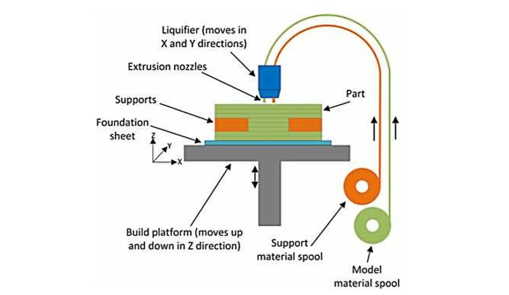
Fig. Schematic Diagram of FDM Process
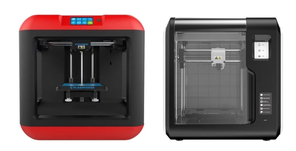
Fig. Flashforge Finder FDM Style 3D Printer
Support Structure: Support structure is essential for creating geometries with overhangs in FDM because melted thermoplastic cannot be deposited on thin air. Surfaces printed on support will generally be of lower surface quality than the rest of the part. For this reason, it is recommended that the part is designed in such a way to minimize the need for support.
Support is usually printed in the same material as the part. Support materials that dissolve in liquid also exist, but they are used mainly in high-end desktop or industrial FDM 3D printers. Printing on dissolvable supports improves significantly the surface quality of the part, but increases the overall cost of a print.
FDM parts are usually not printed solid to reduce the print time and save material. Instead, the outer perimeter is traced using several passes, called the shell, and the interior is filled with an internal, low-density structure, called the infill. Infill and shell thickness affect greatly the strength of a part. For desktop FDM printers, the default setting is 25% infill density and 1 mm shell thickness, which is a good compromise between strength and speed for quick prints.
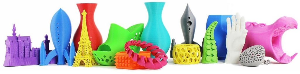
Fig. Objects that are printed with FDM
Design and Slicing: Just like any other form of 3D Printing, the CAD Model is developed using any 3D Design softwares like Solidworks, CATIA, NX, Fusion 360 etc. and the model is exported in STL file format. The STL file is then sliced to generate the GCode using the Slicing Softwares. Either the proprietary slicing software that comes with the printer manufacturer or the open sourced slicing softwares like Ultimaker Cura can be used. Cura has gained a lot of popularity in the community due to more features being added in every release and which is also free to use.
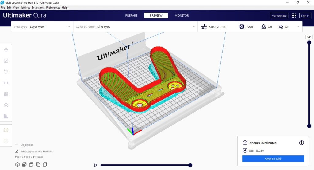
Fig. Ultimaker Cura Slicer software interface and Slicing operation
The sliced file contains the instructions for X, Y and Z movement of the printer head and the printer bed (Y), printing speed, temperature control.
Parameters: Although there are several parameters that need to be set and fine-tuned for best results we will discuss the most important ones below.
a) Print Temperature: This is the vital parameter that controls the melting and deposition of the plastic filament accurately. This depends on the material of the filament being used. Improper print temperature can lead to defects like under extrusion or stringing of the nozzle. Every material has an optimal print temperature range for best strength and dimensional accuracy. For example, PLA prints best at 210 degrees. Beyond 220 degrees causes nozzle oozing and stringing and printing below 200 degrees C will not cause the layers to stick properly and part loses its strength. This trend is observed for other materials also.
b) Layer Height or Layer Resolution: This is the height of each layer used to build the 3D object. FDM printers are capable of printing layer heights of 0.1mm to 0.3 mm. A smaller layer height increases the layers required to build the object hence would consume a lot of time. A higher layer height can reduce print time but layer adhesion gets compromised hence the part strength also gets reduced.
c) Shells/Perimeters: These are the number of outer walls for the object. 2 to 8 perimeters can be used to strengthen the structure.
d) Infill Percentage: Infill is the material that is added inside the body of the object being created. It is not always economical to fill the entire object with the plastic if the object only needs outer appearance and hence infill of 10 to 30% can be used. But this leaves gaps in the internal structure of the object and reduces strength. If strength is required 100% infill is recommended.
e) Infill Pattern: Grid or Hexagonal or Triangular patterns can be used for the infill.
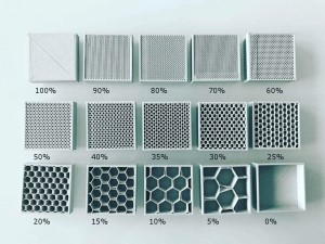
Fig. Grid and Hexagonal Infill patterns with varying infill percentages
Design Constraints:
Minimum Wall thickness: 1.2 mm
Minimum details size: 2 mm (for text/ hole diameters etc)
Layer thickness: 0.1 mm – 0.3 mm
Max dimensions: 650 x 600 x 600 mm. Large parts can be created with assembling individual parts by interlocking designs or gluing together.
Standard Accuracy: ± 0.3% (with lower limit on ± 0.3 mm).
Surface finish: visible layers with texture.
Strength: Strength has to be looked from 4 aspects
1) Material aspect: Below are the tensile strength values of commonly used filament materials. HDT (Heat Deflection temperature is the temperature at which the material tends to lose its strength and rigidity. Shear strength can be considered as 50% of the tensile strength and flexural strength can be considered as 90% of the tensile strength.
Material | Tensile Strength in MPa in XY Direction | Heat Deflection Temperature (degrees centigrade) |
Polycarbonate | 72 | 120 |
PLA | 65 | 50 |
PETG | 53 | 80 |
Nylon (PA) | 48 | 80 |
ABS | 40 | 95 |
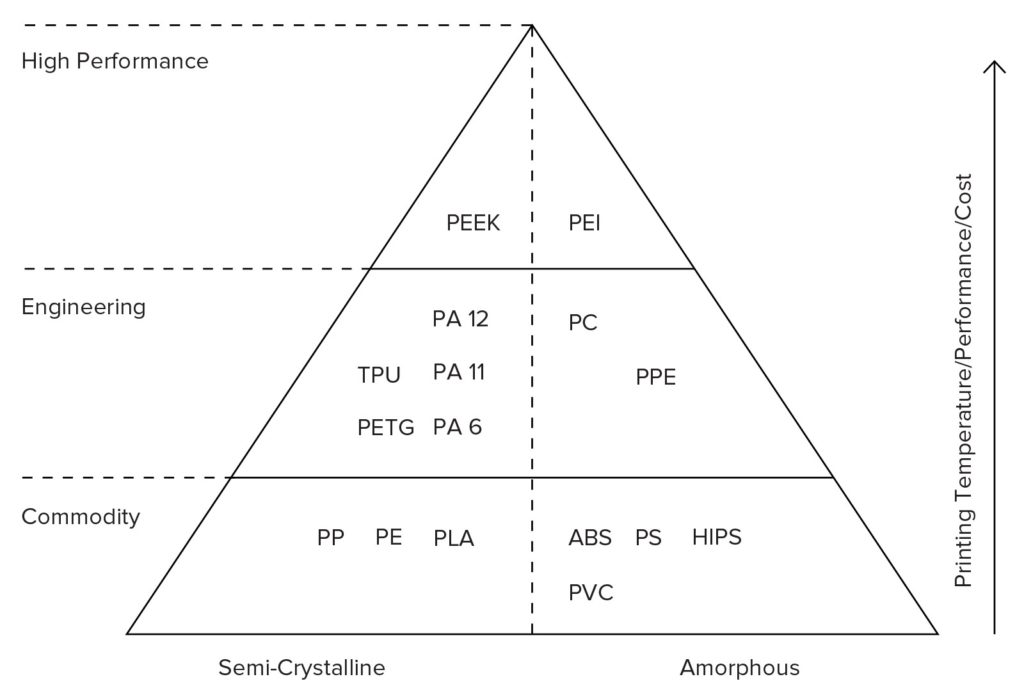
Fig. Material Categorization based on strength and overall performance and use cases
1) Printing Temperature aspect. Improper printing temperature can bring down the specified strength by 50 %.
2) Hence this should be taken care while printing. Geometry and Orientation aspect: Z orientation always gives about half the tensile strength of the same part printed in XY direction irrespective of the layer height used.
3) Layer Height aspect: 0.1 to 0.2 mm layer height gives the maximum strength and increasing the layer height further reduces the strength by 30%.
If all 4 parameters are considered and taken care of properly, we can achieve the strength as stated in the table in point 1.
Materials:
Each material suits a specific application. Applications include Visual Prototypes, Fit validations, Low-Volume Parts, Scale Models of Buildings and Automobiles, Functional Prototypes, Fixtures and holding tools, Sand-casting patterns with less details etc.
Material | Applications |
Polycarbonate | High strength and rigid parts. But generally toxic from environment perspective |
PLA | General Purpose applications such as visual prototyping and design testing. PLA is Biodegradable making it eco-friendly. But material is brittle to failure. Can decompose or loose strength under sunlight. Should be kept away from moisture and water. |
PETG | Substitute for PLA where the part is subjected to moisture and water. |
Nylon | Substitute for PLA where a little bit of flexibility is needed such as snap fits |
ABS | Substitute for PLA where the part is subjected to more than 50 degrees centigrade temperature and less than 100 degrees centigrade. Toxic if ABS fumes are inhaled hence need to be handled with care, hazardous in contact with fire. |
TPU | Rubber like material that can be used for making soft toys. |
There are a lot more materials available in the market and the complete material properties can be viewed here at https://www.simplify3d.com/support/materials-guide/properties-table
Advantages: FDM is cost effective and a wide range of printable thermoplastic materials are available. Large prints can be done up to 750 mm x 750 mm x 750 mm
Limitations:
Dimensional accuracy is not so good (+/- 0.3 mm tolerance). Surface Finish is not so good in FDM and would generally require post processing like sanding, filing and acetone smoothing. Even after post-processing the surfaces typically have roughness value (Ra) of 25 to 125 micrometers.
For more information on our services, please visit our services page: https://www.think3d.in/services/3d-printing/fused-deposition-modeling
© Copyright 2014 – 24 THINK3D. All rights reserved